
Ranger 4WD L4-122 2.0L SOHC (1984)
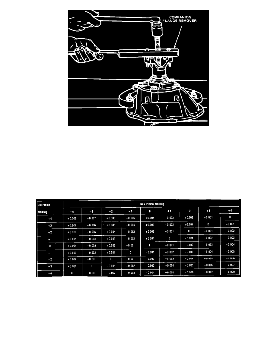
Fig. 4 Removing Companion Flange
1.
Remove drive pinion shaft nut, Fig. 3.
2.
Remove companion flange from drive pinion shaft, Fig. 4.
3.
Using suitable puller, remove pinion seal.
4.
Remove the pinion, bearing, and retainer assembly from carrier housing. Extreme care must be taken not to damage mounting surfaces of
retainer and carrier.
5.
Place protective sleeve on pinion pilot bearing surface and press drive pinion shaft out of pinion retainer.
6.
Using tool T71P-4621-B or equivalent, press pinion shaft out of pinion rear bearing cone.
7.
Clean and inspect all parts as described in ``General Axle Service.''
Drive Pinion Depth of Mesh Setting
Fig. 3 Shim setting chart
Ring gears and pinions are supplied in matched sets only. Matched numbers on both the pinion and ring gear are etched for verification. On the face of
each pinion there is etched either a plus or a minus number, or ``0,'' which indicates the best running position for each particular gear set. This
dimension is controlled by shimming behind the inner pinion bearing cup. A pinion etched with a +3 would require .003 inch less shims that a pinion
etched ``0.'' A pinion etched - 3 would require .003 inch more shims than a pinion etched ``0.'' If the etched figure is ``0'' the shim pack will remain the
same. Refer to chart, Fig. 3. Shims are available in thicknesses of .003 inch, .005 inch, .010 inch and .030 inch.
If old ring and pinion set is to be reused, measure the old shim pack and build a new shim pack to the same dimension. If a baffle is used in the axle
assembly, it is considered a part of the shim pack. Measure each shim separately with a micrometer and add together to get the total shim pack thickness
from the original build up.