
Ranger 4WD L4-134 2.2L DSL (1983)
Valve Clearance: Adjustments
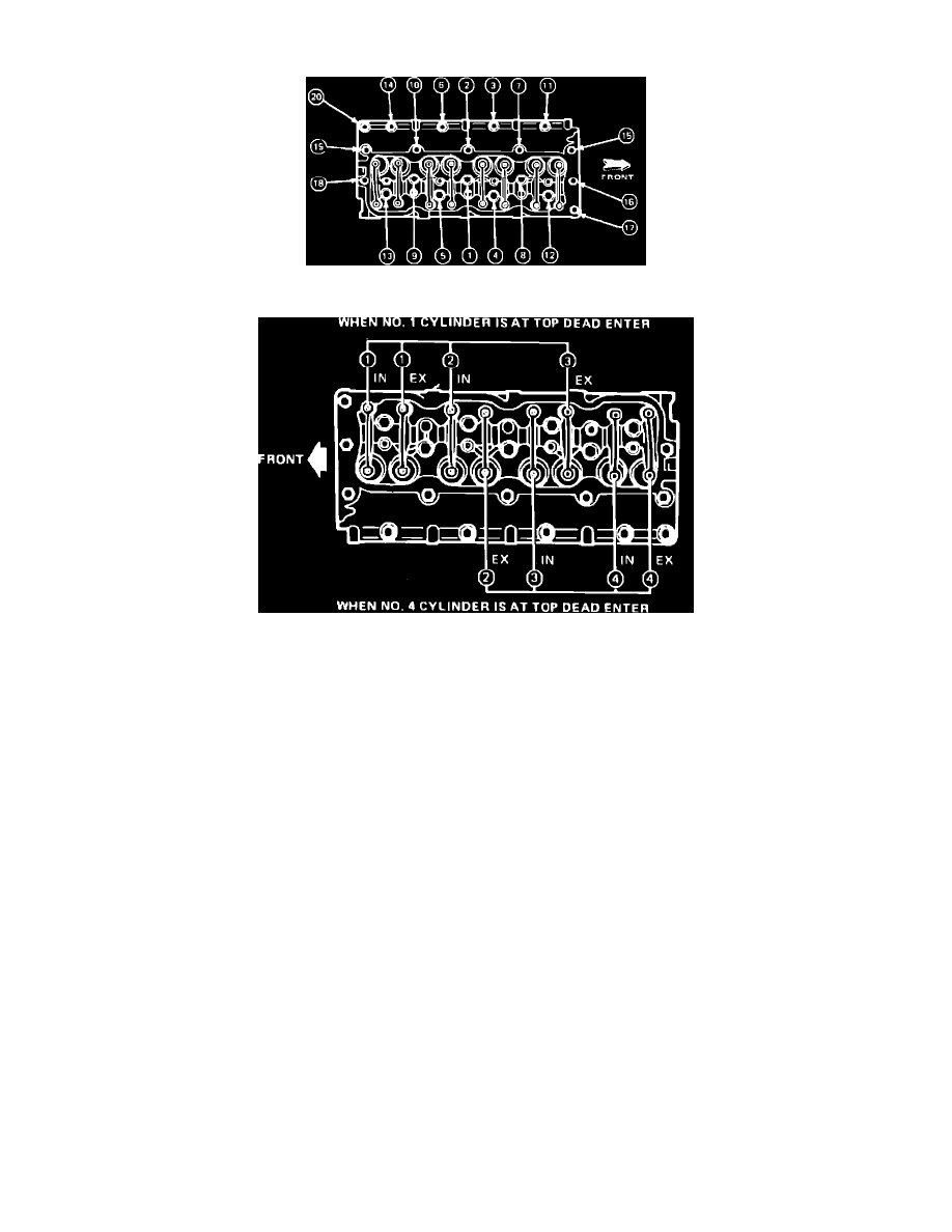
Fig. 5 Cylinder head bolt tightening sequence
Fig. 6 Valve adjustment sequence
1.
Run engine until normal operating temperature is reached, then remove valve cover.
2.
Torque cylinder head attaching bolts to specifications in sequence shown in Fig. 5.
3.
Rotate crankshaft until cylinder No. 1 is at top dead center of compression stroke.
4.
Check valve clearances in sequence, Fig. 6, using a suitable feeler gauge.
5.
Adjust any valve clearances which do not meet specifications as follows:
a. Loosen adjusting screw locknut.
b. Rotate adjusting screw as necessary to bring clearance within specifications.
c. Tighten locknut while holding adjusting screw in position.
d. Recheck valve clearance.
6.
Rotate crankshaft one complete revolution until cylinder No. 4 is at top dead center of compression stroke, then repeat steps 4 and 5.