
Ranger 4WD V6-177 2.9L (1988)
Ignition Lock: Service and Repair
Without Key
The following procedure applies to vehicles where the ignition lock is inoperative or lock cylinder cannot be rotated due to broken or missing ignition
key and the key number is unknown, or the lock cylinder cap is damaged and/or broken so that lock cylinder cannot be rotated.
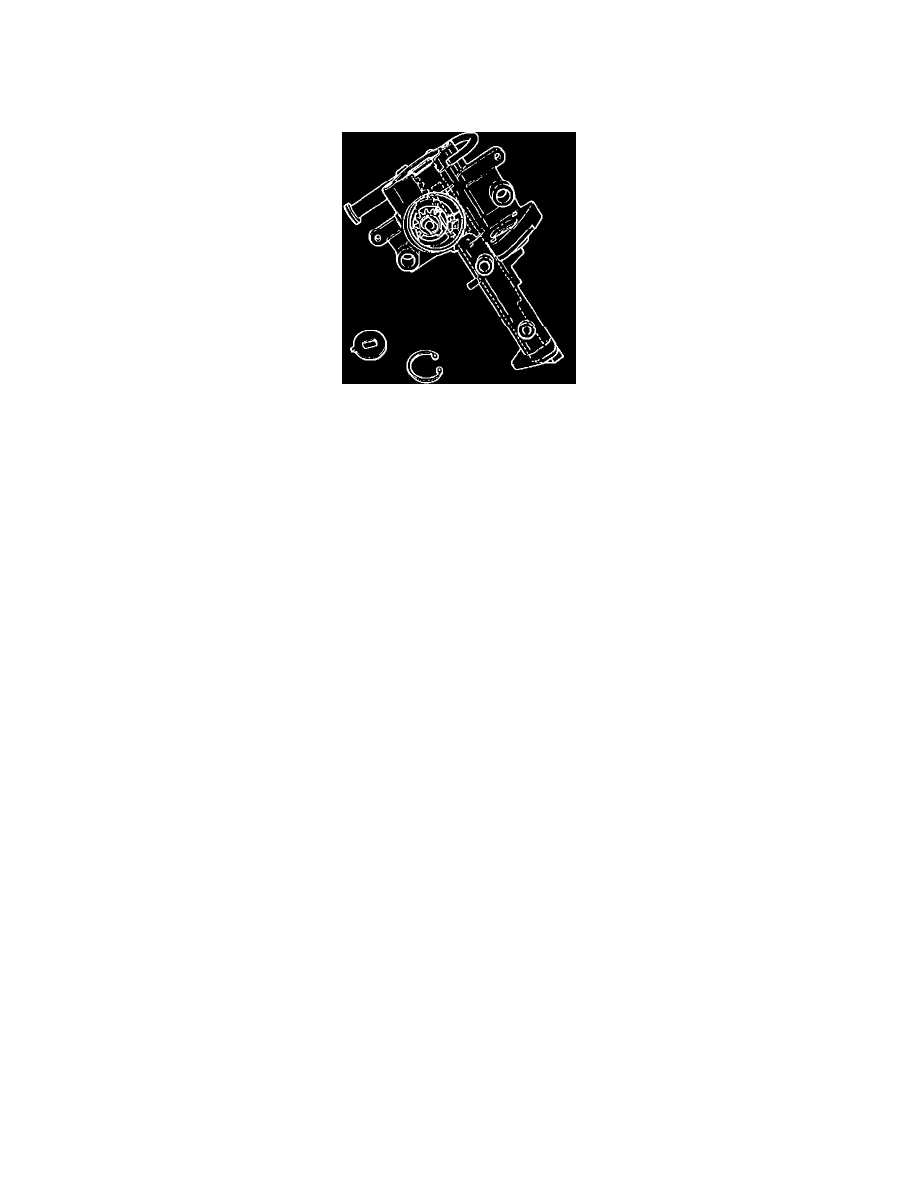
Fig. 3 Ignition Lock Drive Gear.
REMOVAL
1.
Disconnect battery ground cable (two ground cables on diesel engines), then remove steering as follows:
a.
Disconnect battery ground cable (two ground cables on diesel engines).
b.
From underside of steering wheel, remove screws attaching horn pad to steering wheel spokes.
c.
Lift up steering wheel pad, then disconnect horn wires and electrical connectors from pad.
d.
Remove steering wheel attaching bolt and damper, if equipped.
e.
Remove steering wheel using steering wheel remover T67L-3600-A or equivalent, Do not use a knock-off type wheel puller or strike end
of steering shaft, as damage will result.
2.
Remove steering column trim shroud, then disconnect electrical connector from key warning switch.
3.
Drill out retaining pin using a 1/8 inch diameter drill, to a depth of 1/2 inch maximum.
4.
Place a chisel at base of ignition lock cylinder cap, then strike chisel with sharp blows using a suitable hammer to break cap away from lock
cylinder.
5.
Using a 3/8 inch diameter drill, drill down middle of ignition lock key slot approximately 1-3/4 inch until lock cylinder breaks loose from
breakaway base of lock cylinder, then remove lock cylinder and drill shavings from lock cylinder housing.
6.
Remove snap ring, washer and steering column lock drive gear, Fig. 3, noting relationship of tang on lock drive gear to slot in lock cylinder
housing.
7.
Thoroughly clean all drill shavings and foreign materials from casting, then carefully inspect lock cylinder housing for damage. If any damaged is
noted, replace housing.
INSTALLATION
1.
Position lock drive gear in base of lock cylinder housing in same position as noted during removal. Position of drive gear is correct if last tooth
on drive gear meshes with last tooth on rack.
2.
Verify correct drive gear to rack alignment by inserting a flat blade screwdriver in recess of gear and rotating to full counterclockwise position.
After verification, rotate drive gear back to original position.
3.
Install washer and snap ring, noting that flats in recess of drive gear align with flats in washer.
4.
Turn lock cylinder to Run position, depress retaining pin and insert assembly into housing.
5.
Ensure cylinder is fully seated and aligned into interlocking washer, then turn key to Off position to extend cylinder retaining pin into cylinder
housing.
6.
Turn key to check for proper operation in all positions.
7.
Connect key warning switch electrical connector, then install steering column trim shroud.
8.
Install steering wheel as described below, then connect battery ground cable(s).
a.
Position steering wheel on end of steering shaft, aligning mark and flats on steering wheel with mark and flats on steering shaft, and ensuring
that straight ahead steering wheel position corresponds with straight ahead position of front wheels.
b.
If equipped, install damper and align locators with hole in wheel hub.
c.
Install steering wheel attaching bolt and torque to 23-33 ft. lbs.
d.
Connect horn wires and electrical connectors, then install horn pad.