
Ranger 4WD V6-177 2.9L (1988)
Shift Lever: Adjustments
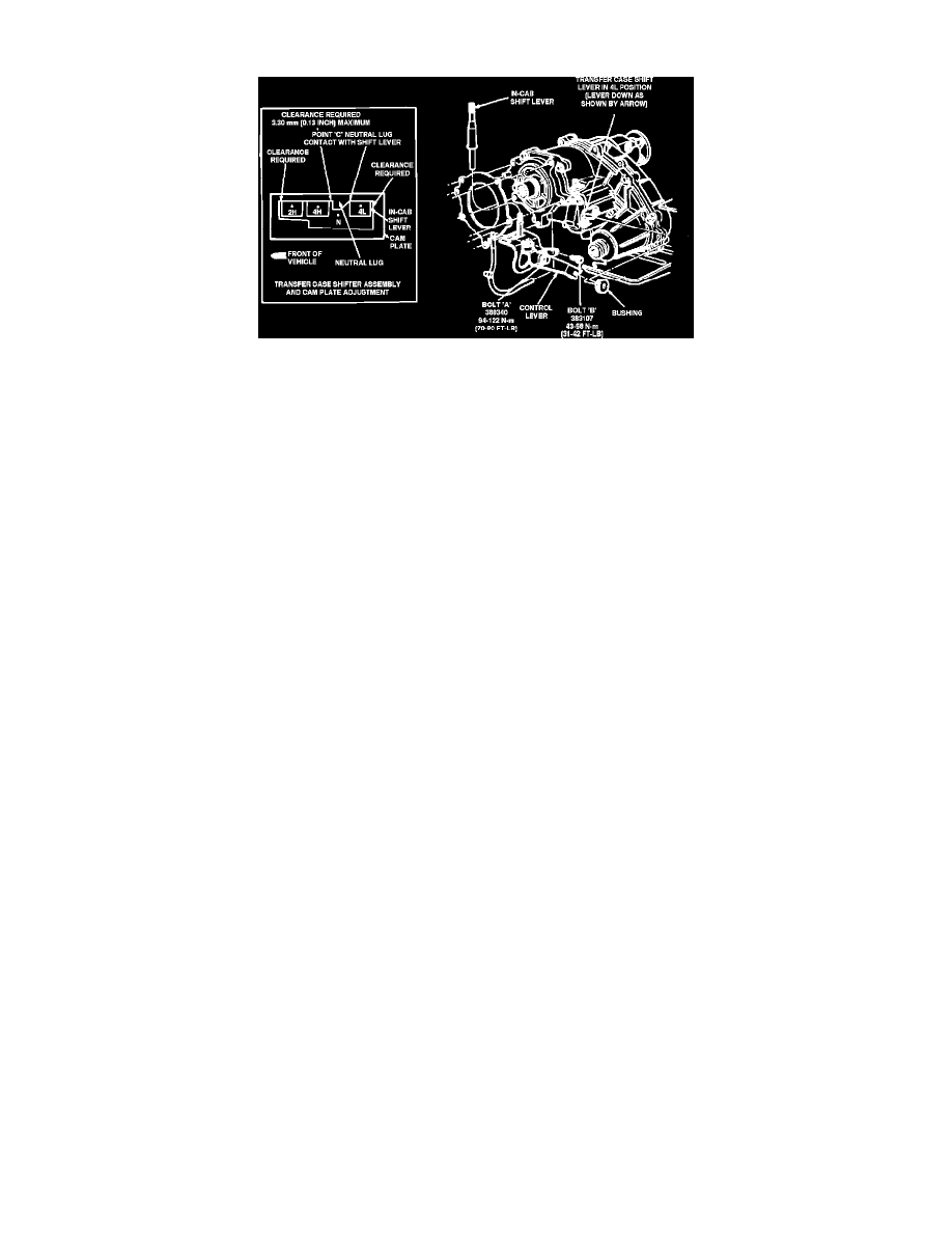
Fig. 5 Shift Linkage Adjustment
1.
Raise shift boot to expose cam plate, loosen bolts A and B, Fig. 5, approximately two turns, then place shift lever in 4L position.
2.
Move cam plate rearward until bottom corner of neutral lug just contacts forward right edge of shift lever (Point C), Fig. 5.
3.
With cam plate positioned as outlined above, torque bolt A to 70-90 ft. lbs., then bolt B to 31-42 ft. lbs.
4.
Place shift lever in all shift positions and check for positive engagement.
5.
Check clearance between shift lever and cam plate with shift lever positioned in 2H, 4H and 4L positions as shown, Fig. 5. Clearance should not
exceed .130 inch. If clearance exceeds specification, repeat adjustment