
Ranger 4WD V6-245 4.0L (1991)
Ignition Control Module: Description and Operation
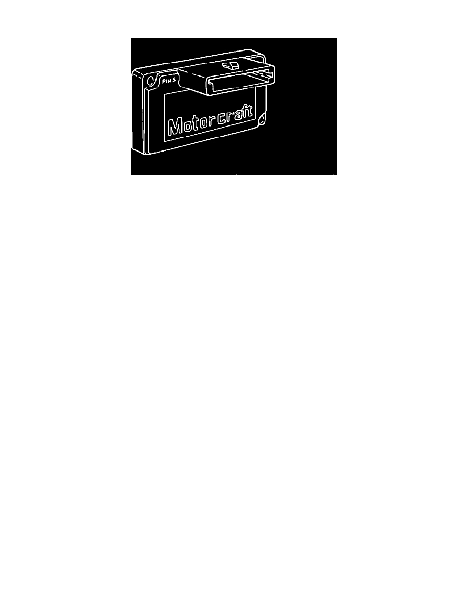
Module And Pin-Out
The EDIS module receives the Variable Reluctance Sensor (VRS) signal from the crankshaft sensor and the Spark Advance Word (SAW) signal from
the EEC IV module. During normal operation, Profile Ignition Pickup (PIP) is sent to the EEC IV module from the EDIS module, providing base timing
and RPM information. The VRS signal provides the EDIS module with the information required to synchronize the ignition coils for proper firing
sequence. The Spark Angle Word (SAW) signal is a pulse width modulated signal and contains the optimum spark timing information. Spark angle is
determined by the EDIS module using a zero excess dwell control routine.
PIN 1 PIP
PIN 2 IDM (IGNITION DIAGNOSTIC MONITOR)
PIN 3 SAW (SPARK ADVANCE WORD)
PIN 4 IGN GRD (IGNITION GROUND)
PIN 5 VRS- (VARIABLE RELUCTOR SENSOR NEGATIVE)
PIN 6 VRS+ (VARIABLE RELUCTOR SENSOR POSITIVE)
PIN 7 VRS SHIELD
PIN 8 VBAT (IGNITION POWER TO COMPONENT)
PIN 9 GND (BATTERY NEGATIVE)
PIN 10 COIL 1 (CYL 1 and 5)
PIN 11 COIL 2 (CYL 2 and 6)
PIN 12 COIL 3 (CYL 3 and 4)