
Ranger 4WD V6-3.0L VIN V Flex Fuel (1999)
Information Bus: Testing and Inspection
Module Configuration
Inspection and Verification (Start Here)
1. visually inspect for obvious signs of electrical damage. Refer to the following chart:
VISUAL INSPECTION CHART
Electrical
^
Central Junction Box (CJB) Fuse 5 (10 A)
^
Damaged wiring harness
^
Loose or corroded connectors
^
4-wheel anti-lock brake control module
^
GEM/CTM
^
PATS Module
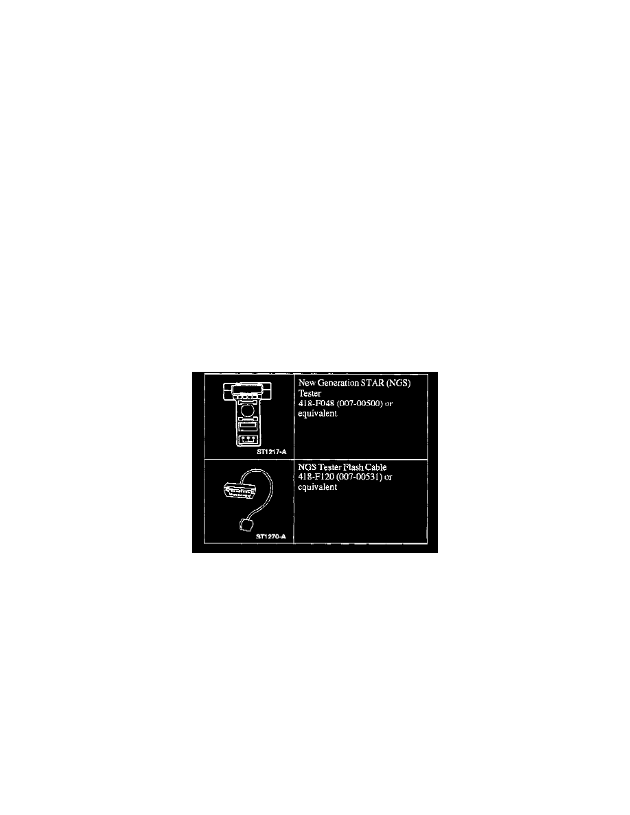
2. If the concern remains after inspection, connect the New Generation STAR (NGS) Tester to the Data Link Connector (DLC) located beneath the
instrument panel and select the vehicle to be tested from NGS Tester menu. If NGS Tester does not communicate with the vehicle:
^
check that the program card is correctly installed.
^
check the connections to the vehicle.
^
check the ignition switch is in RUN position.
If the NGS Tester still will not communicate with the vehicle, refer to Module Communication Network. See: Module Communication Network/System
Precheck
3. Refer to the Symptom Chart. See: Symptom Chart
Diagnostic Schematic and Connector Information
Refer to Vehicle/Diagrams for schematic and connector information. See: Diagrams
Principles of Operation (How Does It Work?)
NOTE:
^
Newly released modules will require configuration after being installed on the vehicle. All configurable modules will be packaged in a kit which
contains a warning label and a multi-language sheet reemphasizing the requirements to configure replacement modules.
^
The Powertrain Control Module (PCM) has to be flash programmed using a flash cable.
Customer Driven Preferences
There are customer preference items that can or need to be configured on this vehicle. These are items that the customer may or may not want to
have enabled. Typically, customer preference items can be toggled on or off by the use of a Ford compatible scan tool. You may need to ask the
customer which preferences they had enabled prior to installation of the new module.
To carry out the customer configuration process, use a Ford Service Function (FSF) card and the NOS Tester. Refer to the Customer Preference
Index for modules on the vehicle that have customer preference items. See: Customer Preference Index
Configure the items as needed with a Ford compatible scan tool.
Customer Preference Index