
Taurus L4-153 2.5L HSC (1986)
3.
If no voltage is present, the wiring is at fault. Service the faulty circuit.
4.
Remove jumper wire from regulator wiring plug and connect wiring plug to regulator. Repeat Load Test. Refer to illustration of jumper wire
connections in Under Voltage, External Voltage Regulator System.
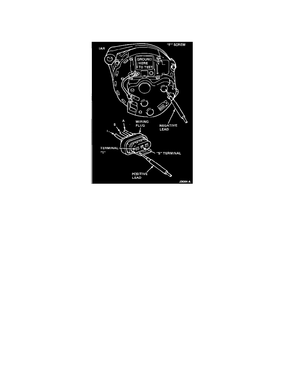
IAR System
1.
Disconnectthe wiring plug from the regulator. Connect a jumper wire from the regulator "A" terminal to the wiring plug "A" lead. Add a jumper
wire from the regulator "F" screw to the alternator rear housing.
2.
With the engine idling and the voltmeter, Rotunda Number 014-00407, negative lead cone to the alternator rear housing, connect the voltmeter
positive lead to the "S" terminal and then to the "I" terminal of the regulator wiring plug. The voltage at the "S" circuit should read approximately
one-half that of the "I" circuit. If voltage readings are normal, remove the jumper wire. Replace the regulator and connect the wiring plug to the
regulator. Repeat the load test.
3.
If no voltage is present, remove the jumper wires and service the faulty wiring circuit or alternator.
4.
Connect the voltmeter positive lead to the positive battery terminal. Connect the wiring plug to the regulator. Repeat the Load Test.