
Taurus V6-182 3.0L DOHC SHO (1992)
Refrigerant Pressure Sensor / Switch: Description and Operation
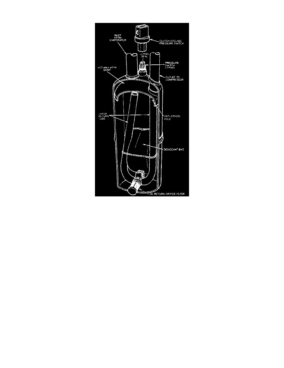
Fig 8 Suction Accumulator/Drier Dome Type
DESCRIPTION
The clutch cycling pressure switch is mounted on a Schrader valve-type fitting on the top of the suction accumulator/drier assembly. A valve
depressor, located inside the threaded end of the pressure switch, presses the Schrader valve stem down as the switch is mounted and allows the
suction pressure inside the accumulator/drier canister to act on the switch.
OPERATION
The electrical switch contacts are normally open when the suction pressure is approximately 169 kPa (24.5 psi). They will close when the suction
pressure rises to approximately 276-324 kPa (40-47 psi) or above. Lower ambient temperatures, below approximately 9° C (48° F), during cold
weather seasons, will also open the clutch cycling pressure switch contacts due to the pressure/temperature relationship of the refrigerant in the
system. The electrical switch contacts control the electrical circuit to the compressor magnetic clutch coil. When the switch contacts are closed, the
magnetic clutch coil is energized and the A/C clutch is engaged to drive the compressor. When the switch contacts are open, the compressor
magnetic clutch coil is de-energized, the A/C clutch is disengaged and the compressor does not operate. The clutch cycling pressure switch, when
functioning properly, will control the evaporator core pressure at a point where the plate/fin surface temperature will be maintained slightly above
freezing which prevents evaporator icing and the blockage of airflow.