Taurus V6-182 3.0L DOHC SHO (1992)

INSTALLATION INSTRUCTIONS
Part Name...................................................................................................................................................................................................................Class
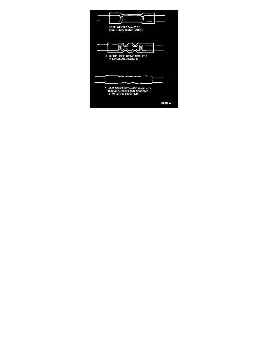
Butt Connector Gauge: 18-22, Color: Red.........................................................................................................................................................................C
Butt Connector Gauge: 14-16, Color: Blue........................................................................................................................................................................C
Butt Connector Gauge: 10-12, Color: Yellow....................................................................................................................................................................C
Steering Column
If the accident involved an air bag deployment, the steering column may have been loaded sufficiently to deform steering column mounting brackets
or damage column wiring. An inspection should be made of the column structure and clockspring wiring to ensure that any damaged components are
replaced.
Air Bag System
Prior to attempting diagnostic prove out on a serviced vehicle thoroughly check all sensors and wiring for damage and pinch condition which may
cause the diagnostic module internal fuse to blow.
After all service, verify the air bag indicator. This means turn the ignition switch to RUN and count the flashes only after the code (series of flashes)
has cycled twice. If the air bag indicator comes on continuously for four to eight seconds and then goes out, the system is functioning properly and all
faults have been serviced.
