
Taurus V6-182 3.0L VIN 1 FI Flex Fuel (1997)
Camshaft: Service and Repair
Removal
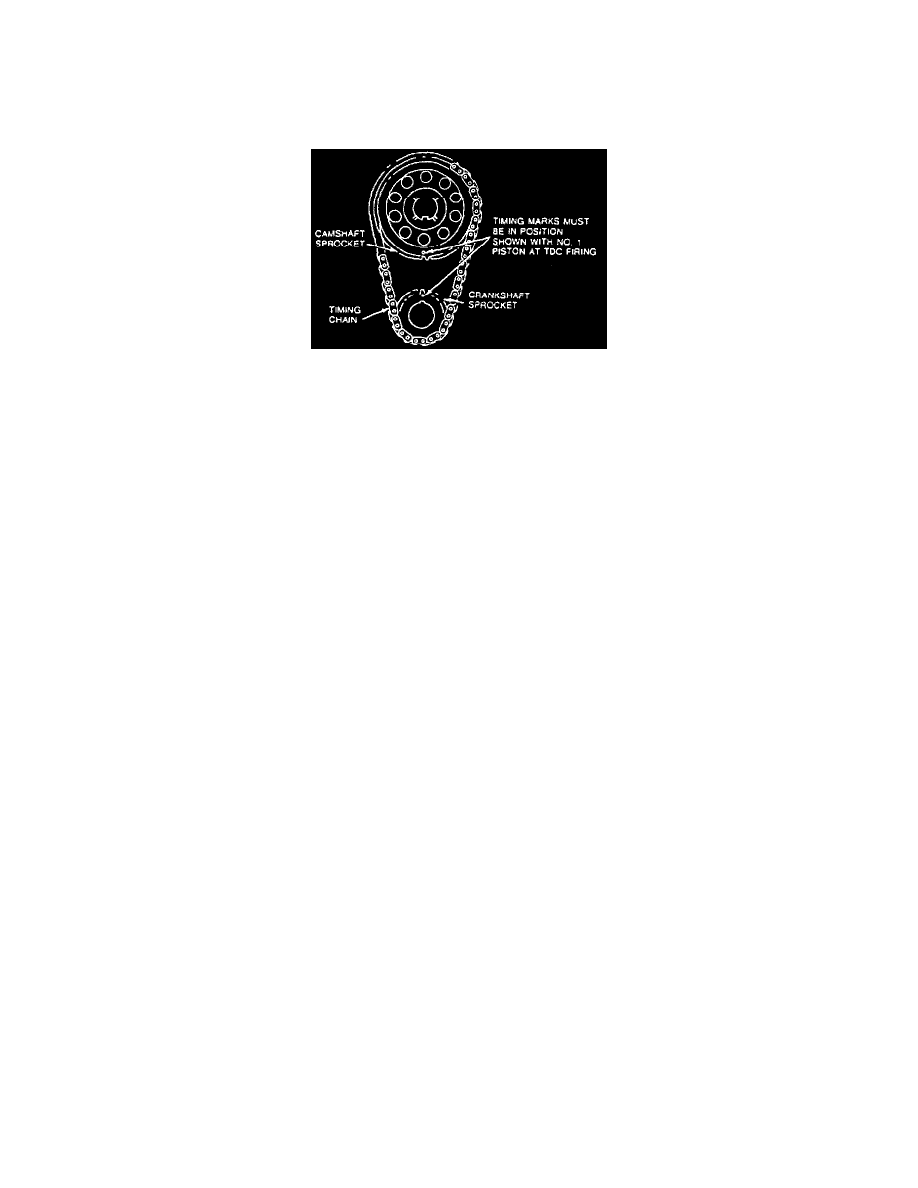
Fig. 8 Timing Chain Alignment
1. Remove engine from the vehicle and place on a work stand.
2. Rotate crankshaft to zero degrees at top dead center (TDC) on the compression stroke.
3. Remove upper intake manifold.
4. Disconnect engine control sensor wiring retainers from valve cover stud bolts. Carefully disconnect engine control sensor wiring from each fuel
injector and position the engine control sensor wiring out of the way.
5. Remove ignition wires from spark plugs. Refer to Powertrain Management.
5. Remove ignition wire separators from valve cover stud bolts.
6. Remove camshaft position sensor housing retaining bolt and washer. Remove camshaft position sensor housing.
7. Remove ignition coil from rear of LH cylinder head.
8. Remove valve covers.
9. Loosen cylinder No.3 intake valve rocker arm seat retaining bolt and rotate rocker arm off of push rod and away from top of valve stem. Remove
push rod.
10. Remove generator (GEN), brackets, drive belt tensioner and drive belt.
NOTE: Lower intake manifold may be removed with fuel injection supply manifold and fuel injector in place as an assembly.
11. Remove intake manifold retaining bolts using a Torx head socket. Before attempting to remove lower intake manifold, break the seal between the
lower intake manifold and cylinder block. Wedge a large pry bar or similar tool between lower intake manifold and cylinder block. Pry upward on
tool using lug on top of engine front cover as a leverage point.
12. Loosen rocker arm seat retaining bolts enough to allow the rocker arms to be lifted off the push rods and rotated to one side.
13. Remove push rods. Identify each push rod location. The push rods should be installed in their original location and position during assembly.
14. Remove tappet guide plate and retainer bolts. Remove tappet guide plate and retainer from valve tappet valley.
15. Remove valve tappet guide plate from valve tappets by lifting straight up.
NOTE: If the valve tappets are stuck in the bores due to excessive varnish or gum deposits, it may be necessary to use a claw type tool to aid
removal. Rotate the valve tappet back and forth to loosen it from the deposits.
16. Remove valve tappets by grasping each valve tappet and pulling in line with bore.
17. Remove crankshaft pulley retaining bolts and remove crankshaft pulley.
18. Remove crankshaft damper retaining bolt and washer. Remove damper using Crankshaft Damper Remover T58P-6316-D and Vibration Damper
Remover Adapter T82L-6316-B.
19. Remove oil pan. Discard oil pan gasket.
NOTE: Water pump may be removed with engine front cover as an assembly. Do not remove bolts No. 11 through 15 to remove as an assembly.
Refer to engine front cover for proper procedures.
20. Remove engine front cover retaining bolts.
21. Remove engine front cover and discard old engine front cover gasket:
CAUTION: Use care to not damage machined surfaces when removing engine front cover. Only drive pry bar enough to break gasket seal.
A. Place a dull, thin-bladed pry bar or similar device between engine front cover and cylinder block and tap to break seal.
B. Walk engine front cover off alignment dowels using a soft rocking motion. Use crankshaft seal protector if available.
22. Align marks on camshaft sprocket and crankshaft as shown.