
Taurus V6-232 3.8L (1989)
4.
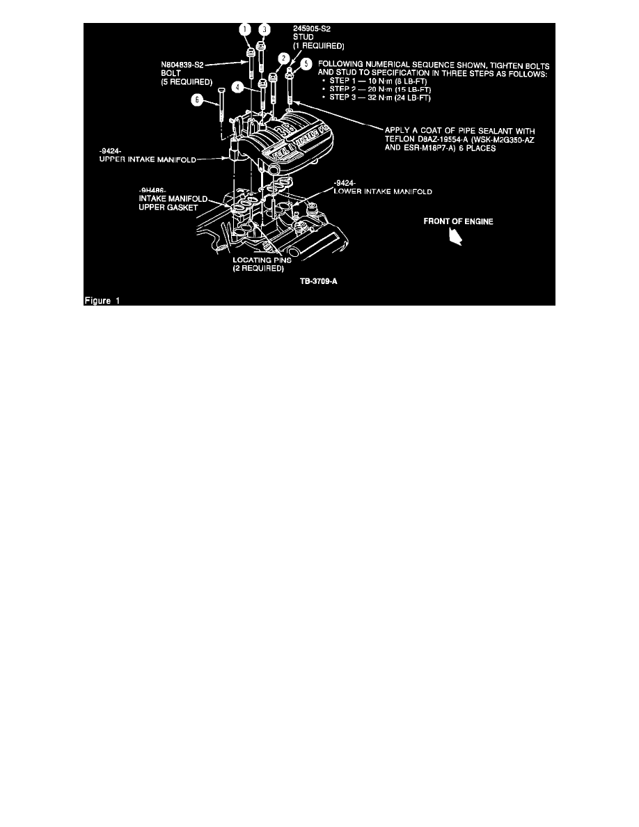
Tighten in sequence in three (3) steps starting with the four center bolts to the following specifications.
a.
10 N-m (8 lb.ft.)
b.
20 N-m (15 lb.ft.)
c.
32 N-m (24 lb.ft.)
5.
Position alternator bracket and install two retaining bolts to water pump and alternator. Install alternator bracket to upper intake manifold and
tighten nut to 19 lb. ft. (25 N-m).
6.
Connect EGR Valve to EGR tube making sure tube is properly seated in EGR Valve. Connect EGR Valve to upper intake manifold and install
bolts. Tighten to 19 lb. ft. (25 N-m).
7.
Install canister purge lines to fittings on throttle body.
8.
Connect PCV hose to rear of upper intake manifold.
9.
Connect vacuum hoses to vacuum tree, EGR Valve and Fuel Pressure Regulator.
10.
Position throttle linkage bracket with cables to upper intake manifold. Install two retaining bolts and tighten to 13 lb. ft. (17 N-m). Connect
throttle cable and AXOD transmission cable cable to throttle body.
11.
Connect electrical connectors at Air Bypass Valve, Throttle Position Sensor, and EGR Position Sensor.
NOTE: If lower intake manifold was removed, fill and bleed cooling system.