
Taurus AWD V6-3.5L (2009)
Brake Lamp: Pinpoint Tests
Pinpoint Test I: All The Stoplamps Are Inoperative
Stoplamps
Pinpoint Tests
Pinpoint Test I: All The Stoplamps Are Inoperative
Refer to Wiring Diagram Set 90, Turn Signal/Stop/Hazard Lamps for schematic and connector information. See: Diagrams/Electrical
Diagrams/Diagrams By Number
Normal Operation - Taurus, Taurus X
The stoplamp switch is supplied voltage through circuit SBP02 (YE/RD) from the Smart Junction Box (SJB). When the brake pedal is applied, the
stoplamp switch routes voltage to the SJB and the high mounted stoplamp through circuit CCB08 (VT/WH).
Sable
The stoplamp switch is supplied voltage through circuit SBP02 (YE/RD) from the SJB. When the brake pedal is applied, the stoplamp switch routes
voltage to the rear lamps and the high mounted stoplamp through circuit CCB08 (VT/WH).
This pinpoint test is intended to diagnose the following:
-
Fuse
-
Wiring, terminals or connectors
-
Stoplamp switch
-
SJB
PINPOINT TEST I: ALL THE STOPLAMPS ARE INOPERATIVE
NOTICE: Use the correct probe adapter(s) when making measurements. Failure to use the correct probe adapter(s) may damage the
connector.
-------------------------------------------------
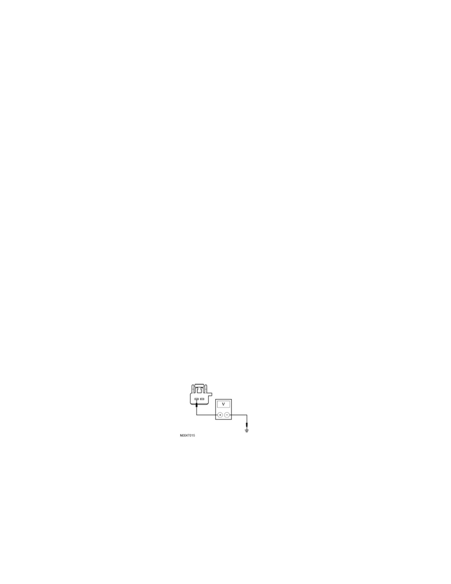
I1 CHECK FOR VOLTAGE TO THE STOPLAMP SWITCH
-
Ignition OFF.
-
Disconnect: Stoplamp Switch C278.
-
Measure the voltage between the stoplamp switch C278-2, circuit SBP02 (YE/RD), harness side and ground.
-
Is the voltage greater than 10 volts?
Yes
GO to I2.
No
VERIFY the SJB fuse 2 (15A) is OK. If OK, GO to I3. If not OK, Refer to the Wiring Diagrams to identify the possible causes of the circuit short.
-------------------------------------------------
I2 BYPASS THE STOPLAMP SWITCH
-
Connect a fused jumper wire between the stoplamp switch C278-2, circuit SBP02 (YE/RD), harness side and the stoplamp switch C278-1, circuit