
Taurus X FWD V6-3.5L (2008)
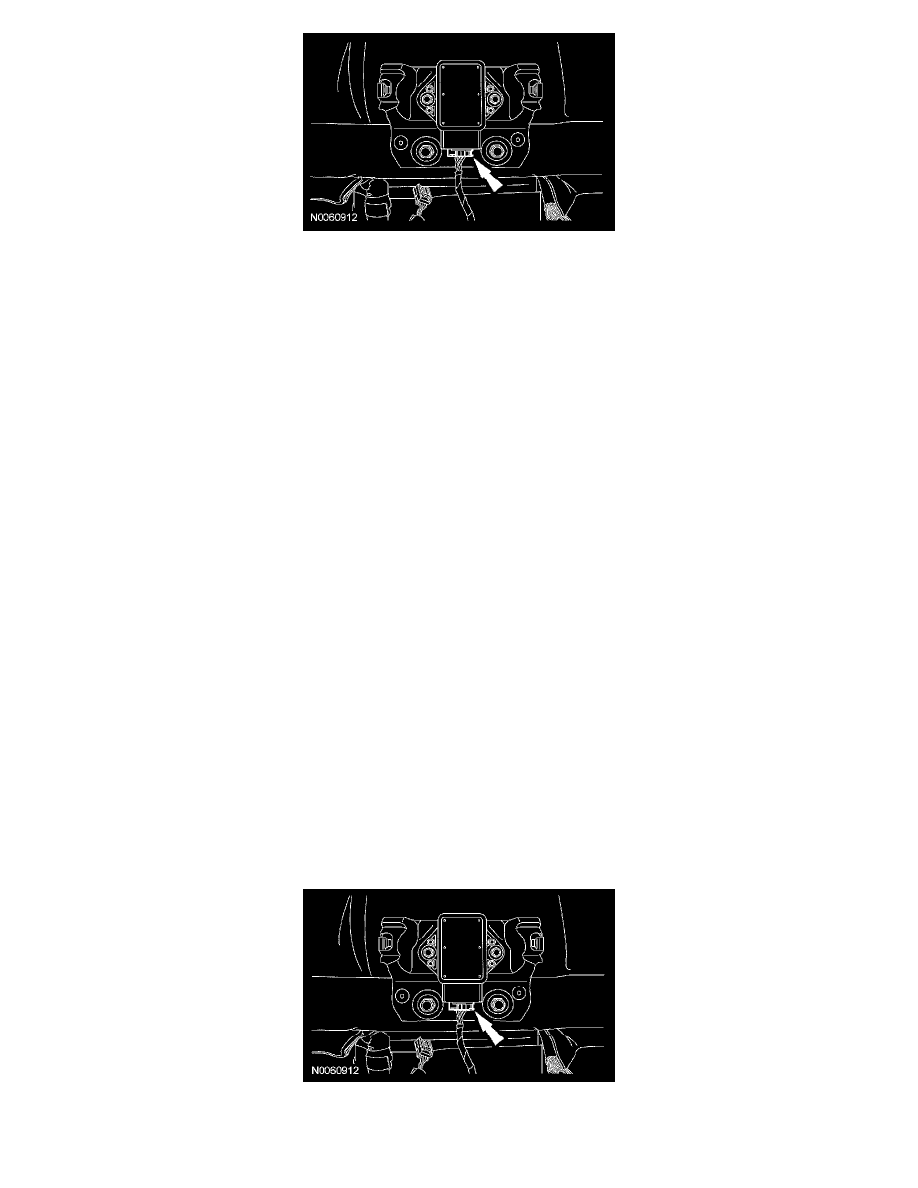
24. Remove the 4 instrument panel center support bolts.
25. CAUTION: To avoid damaging the in-vehicle crossbeam, an assistant is required when carrying out this step.
NOTE:
-
Mark the location of the instrument panel side bolts for correct alignment upon installation.
-
Remove the instrument panel side bolts from one side completely and support the in-vehicle crossbeam before removing the instrument panel
side bolts from the opposite side.
-
Make sure that all electrical connectors and wiring are not hindered before removing the in-vehicle crossbeam.
Remove the in-vehicle crossbeam.
-
Remove the 6 instrument panel side bolts.
-
Transfer parts as needed.
Installation
1. CAUTION: To avoid injury or damage to the in-vehicle crossbeam, the help of an assistant is required to carry out this step.
NOTE: Make sure that all electrical connectors and wiring are correctly routed when installing the in-vehicle crossbeam.
Position the in-vehicle crossbeam into the vehicle and install, but do not tighten, the following:
-
Six instrument panel side bolts.
-
Four instrument panel center support bolts.
-
Three instrument panel upper cowl bolts.
2. NOTE: Align the instrument panel side bolts with the instrument panel side bolt markings.
Tighten the 6 instrument panel side bolts.
-
Tighten to 40 Nm (30 lb-ft).
3. Tighten the 4 instrument panel center support bolts.
-
Tighten to 25 Nm (18 lb-ft).
4. Tighten the 3 instrument panel upper cowl bolts.
-
Tighten to 25 Nm (18 lb-ft).
5. Connect the stability control sensor cluster electrical connector.
6. Connect the small RCM electrical connector.