
Tempo L4-122 2.0L DSL (1984)
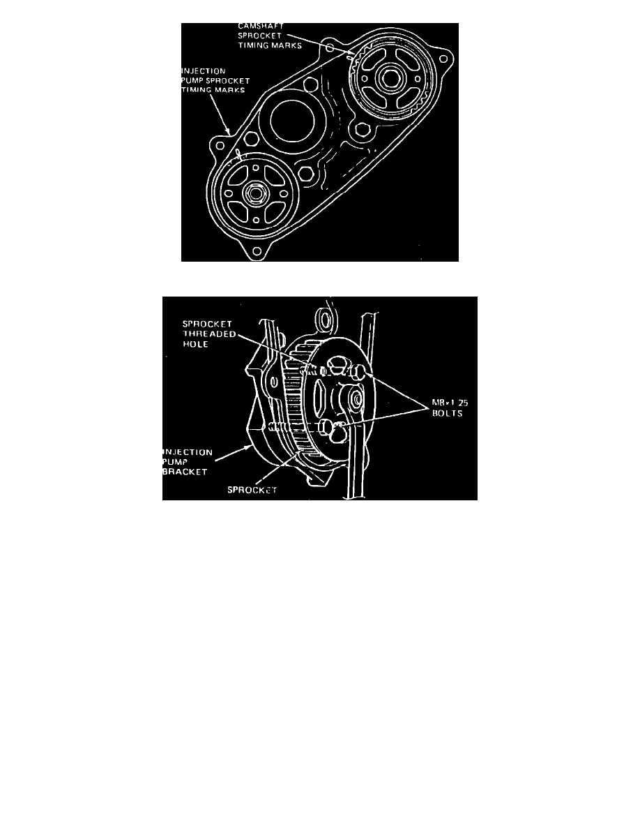
Fig. 18 Camshaft and injection pump timing marks
Fig. 22 Injection pump sprocket removal
1.
Disconnect battery ground cable located in luggage compartment.
2.
Disconnect air inlet duct from air cleaner and intake manifold. Install cap, Fig. 2, onto intake manifold.
3.
Remove rear timing belt cover and flywheel timing mark cover.
4.
Remove rear timing belt as described under ``Rear Timing Belt, Replace''.
5.
Disconnect throttle and speed control cable, if equipped.
6.
Disconnect vacuum lines from altitude compensator and cold start diaphragm.
7.
Disconnect fuel supply and return lines from injection pump.
8.
Disconnect electrical connector from fuel cut-off solenoid.
9.
Remove injection lines from injection pump and nozzles. Cap all lines and fittings with cap set No. T84P-9395 or equivalent, Fig. 3.
10.
Rotate injection pump sprocket until injection pump and camshaft sprocket timing marks align with their marks, Fig. 18.
11.
Install two M8 x 1.25 bolts into injection pump sprocket holes, Fig. 22, to secure injection pump sprocket. Remove injection pump sprocket bolt.
12.
Using tool Nos. T77F-4220B1 and D80L-625-4 or equivalents, remove injection pump sprocket.
13.
Remove bolt securing injection pump to pump front bracket.
14.
Remove injection pump nuts, then the injection pump.
15.
Reverse procedure to install.