
Tempo L4-122 2.0L DSL (1984)
^
Charge indicator gauge ^ Loose or worn alternator belt ^ Adjust tension or replace belt shows discharge ^ Open or
grounded wiring ^ Service as required
^
Improper wiring hook-up ^ Service or replace wiring
^
Alternator ^ Service as required
^
Regulator ^ Replace
^
Charge indicator gauge wiring ^ Service as required and connections
^
Gauge ^ Replace gauge
^
Other vehicle electrical ^ Service or replace as required systems malfunctions
Continue through the Diagnosis Guides until service has been made. Then, again test the system to see if service has corrected the system concern.
Testing
A voltmeter (0-20 or 0-30 volt scale), ohmmeter Rotunda Number 059-00010 (needle indicator type), jumper wires and a test lamp (12 volt) are the only
tools required to perform an accurate check of the complete charging system. The meters should be calibrated once a year and the date of calibrations
stamped on the meter face. It is recommended that this practice be followed by all technicians to maintain their meters at acceptable accuracy.
The tests are divided into "On Vehicle" and "On Bench" test procedures. The "On Bench" procedures are described under the applicable component
Section.
Troubleshooting or diagnosis is required before actual service can be made in the electrical system. Even where an obvious condition makes the
replacement of a unit necesary, find out why the unit failed. When a problem is diagnosed correctly, unnecessary service is prevented, the time the
vehicle is out of service will be decreased, and the service performed will be permanent.
On Vehicle Tests
Before performing charging system tests on the vehicle, note the condition such as: slow cranking, battery dead, top of battery wet, ammeter shows
excessive charge at all times or no charge, alternator warning lamp does not come on or never goes out. This information will aid in isolating the part of
the system causing the concern. (Refer to Section 31-02 for battery warnings and cautions.)
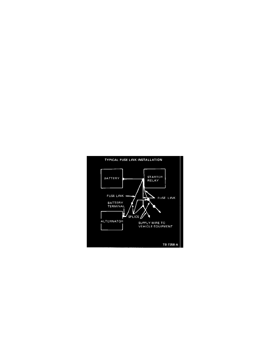
Figure 5
Visual Inspection
1.
Check the fuse link (Figure 5) located between the starter relay and the alternator. If burned, determine cause, service the system and replace fuse
link.
2.
The battery must be in proper state of charge. Check the battery posts and battery cable terminals for clean and tight connections. Remove the
battery cables (if corroded), clean and install them securely.
3.
Check for clean and tight wiring connections on the alternator, regulator and engine.
4.
Check the alternator belt tension and tighten to specification (if necessary). Refer to specifications.
Battery Drain Test
1.
Connect a 12 volt test lamp in series with the positive terminal of the battery. Test with all switches OFF. Do not be misled by clock time keeping
current.