
Tempo L4-122 2.0L DSL (1984)
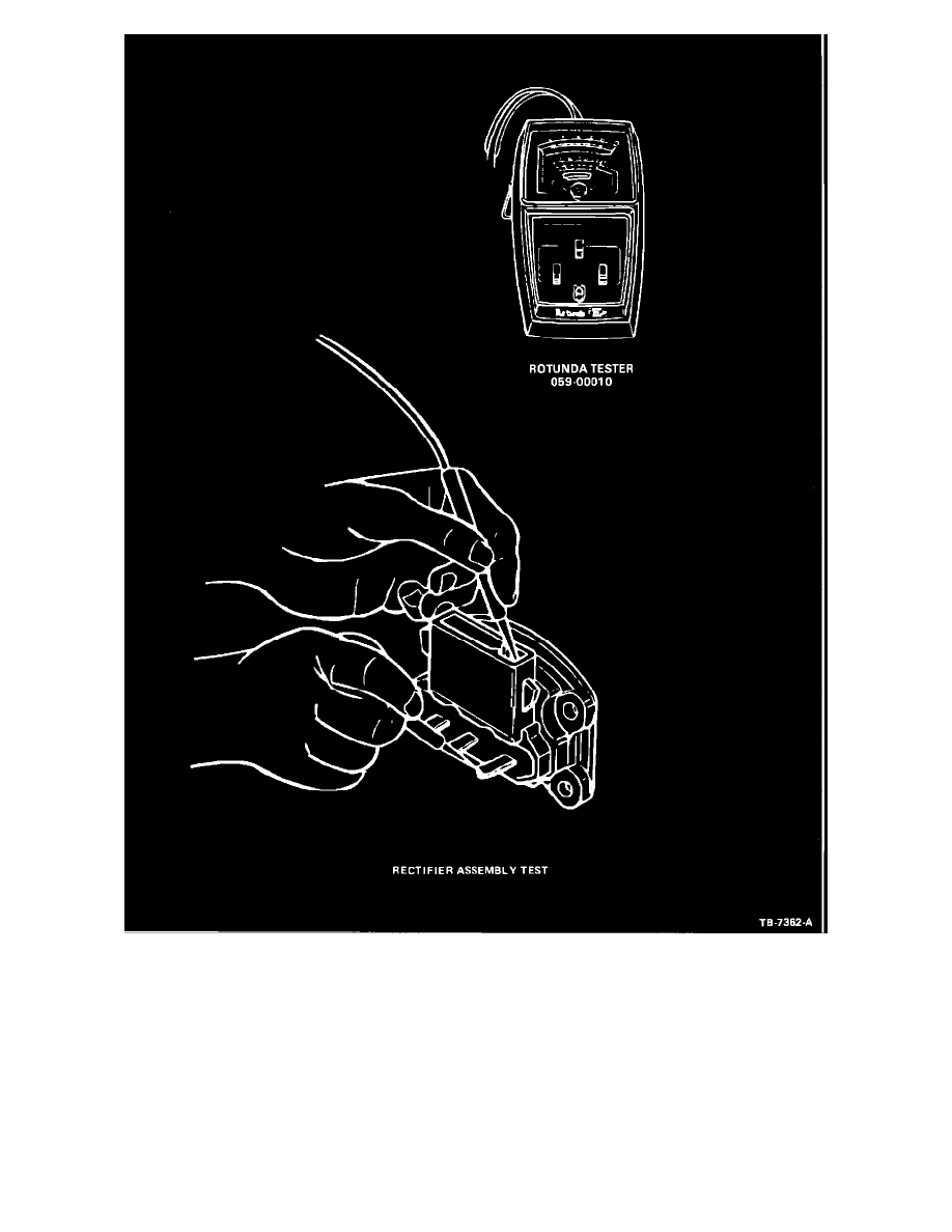
Figure 9
1.
To test the positive diodes, contact one probe to one of the rectifier assembly B+ blade terminals and contact each of the three
stator terminals with the other probe (Figure 9). Reverse the probes and repeat the test. All diodes should show a low reading of
about (7) ohms in one direction and an infinite reading (no needle movement) with the probes reversed. This reading may be
checked against a good rectifier if one is available.
2.
Perform the preceding tests for the negative diodes by contacting the rectifier assembly base plate and the three stator terminals.
3.
If the meter readings are not as specified, replace the rectifier assembly.
Radio Suppression Capacitor Open or Short Test
NOTE:
This is an open or short circuit test only and does not measure capacitance value. Actual capacitance value should be measured