
Tempo L4-122 2.0L DSL (1984)
be replaced.
3.
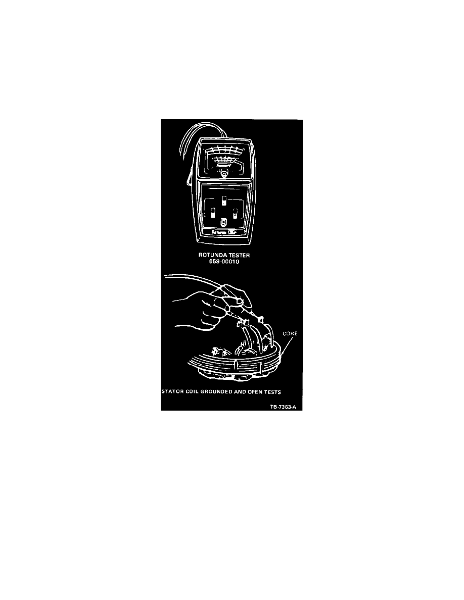
Repeat the test for each of the stator leads (Figure 10). Do not touch the metal probes or stator leads with the hands. Such
contact will result in an incorrect reading.
Stator Coil Open Test
This test determines if there is an open stator circuit. Disconnect the stator from the rectifier assembly. Put the ohmmeter "Multiply
By" setting at 1.
WARNING:
A SINGLE OPEN PHASE CONNECTION WILL NOT BE DISCOVERED BY THIS TEST ON ALTERNATORS
HAVING A "DELTA" CONNECTED STATOR.
Figure 10
1.
Connect one ohmmeter probe to a stator phase lead (Figure 10) and touch the other probe to another stator lead. Check
the meter reading.
2.
Repeat this test with the other two stator lead combinations. If no meter movement occurs (infinite resistance) on a lead
paired with either of the other phase leads, that phase is open and the stator must be replaced.
Rotor Open or Short Test
Remove the rotor from the alternator. Put the ohmmeter "Multiply By" setting at 1 and calibrate the meter as described.
1.
Contact each ohmmeter probe to a rotor slip ring. The meter reading should be 2.0 to 3.9 ohms.
2.
A higher reading indicates a damaged slip ring welded connection or a broken wire.
3.
A lower reading indicates a shorted wire or slip ring. Replace the rotor if it is damaged and cannot be serviced.
4.
Contact the ohmmeter probe to a slip ring and the other probe to the rotor shaft. The meter reading should be infinite
(no needle movement).