
Tempo L4-122 2.0L DSL (1984)
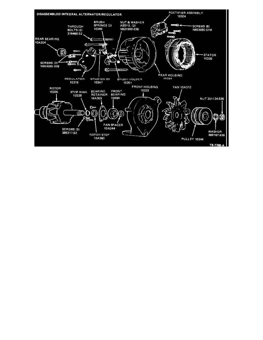
Figure 12
Disassembly
NOTE:
All of the following disassembly steps may not be necessary to perform a particular test or service. Perform only
those steps that apply in your case. See Figure 12 for a full disassembled view of the integral alternator/
regulator assembly. On alternators with fan shield, remove attaching clip and then remove fan shield.
1.
Remove the four screws (T20 TORX type head) attaching the regulator to the alternator rear housing. Remove the
regulator, with brush holder attached, from the alternator.
2.
Remove the two screws (T20 TORX type head) attaching the regulator to the brush holder. Separate the regulator,
attaching nuts, brushes and brush springs from the brush holder.
3.
Scribe a line across the end housings and stator laminated core for reference during assembly.
4.
Remove the three through bolts.
5.
Separate the front housing and rotor assembly from the stator and rear housing. It may be necessary to tap the front
housing with a plastic tipped hammer to loosen the front housing from the stator core.
6.
Remove the three stator lead terminals from the rectifier. Unsolder the connections using a 100 watt soldering iron. Do
not allow the soldering iron to overheat the rectifier. Use a needle nose plier to pull the stator lead terminals upwards
from the rectifier assembly. Separate the stator from the rear housing.
7.
Remove the four rectifier assembly attaching screws (T20 TORX type head) and remove the rectifier assembly from the
housing.
8.
Using a suitable arbor press, remove the bearing from the rear housing. Support the housing close to the bearing boss to
prevent housing damage.