
Tempo L4-122 2.0L DSL (1984)
Ignition Switch: Service and Repair
MODELS LESS PASSIVE RESTRAINT SYSTEM
1. Disconnect battery ground cable, then remove five steering column shroud attaching screws.
2. Remove two bolts and two nuts attaching steering column to column bracket, then lower steering column assembly to seat and remove column
shrouds.
3. Disconnect ignition switch wire connector, then rotate ignition switch lock cylinder to the Run position.
4. Using a {1-8} inch drill bit, drill out shear bolts retaining ignition switch to lock cylinder housing.
5. Remove the two shear bolts using an easy out.
6. Detach ignition switch from actuator pin, then remove switch.
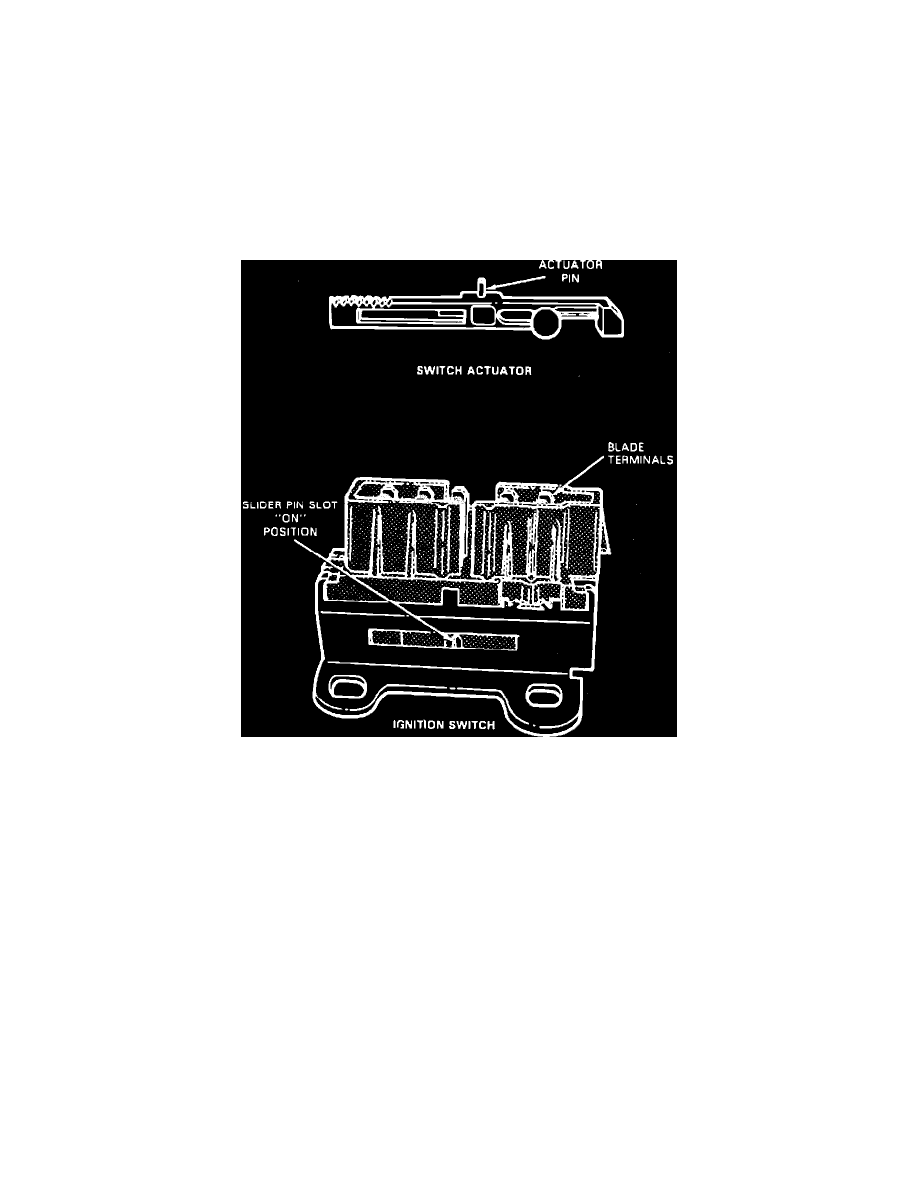
7. Check to ensure that ignition switch actuator pin slot and ignition switch lock cylinder are in the Run position. Replacement ignition switches are
set in the Run position. The Run position on the ignition switch lock cylinder is located approximately 90° from the lock position.
Fig. 1 Ignition switch
8. Position ignition switch on actuator pin. It may be necessary to move switch slightly to align switch to column mounting bolt holes, Fig. 1.
9. Install and tighten shear bolts until heads break off.
10. Connect wire connector to ignition switch, then connect battery ground cable and check ignition switch for proper operation.
11. Position upper shroud on column, then raise steering column and install column mounting bracket to instrument panel attaching bolts. Torque bolts
to 15 to 25 ft. lbs.
12. Position lower shroud on column and install attaching bolts.
MODELS W/PASSIVE RESTRAINT SYSTEM
1. Park vehicle with wheels in the straight ahead position. Turn ignition switch to ``Lock'' position and rotate steering wheel 16° counterclockwise
until locked into position.
2. Disconnect battery ground cable.
3. Remove five steering column shroud attaching screws.
4. Remove two bolts and two nuts holding steering column assembly to steering column bracket assembly. Lower steering column to seat.
5. Remove steering column shrouds.
6. Disconnect ignition switch electrical connectors slip ring connector to column harness.
7. Drill out break-off head bolts attaching switch to lock cylinder. Use a {1-8} inch drill bit.
8. Remove two bolts using a ES-3 easy out tool or equivalent.
9. Disengage ignition switch from actuator pin.
10. Reverse procedure to install.