
Tempo L4-122 2.0L DSL (1984)
3.
Install four valve sleeve rings, refer to Fig. 37 A---F and the following steps:
a. Lubricate sleeve tool No. T81P-3504-M1, or equivalent, with automatic transmission fluid type F or equivalent, position tool over valve
assembly, Fig. 37A.
b. Place valve sleeve ring over tool, quickly push down on pusher tool No. T81P-3504-M2, or equivalent, sliding the ring down into the fourth
groove, Fig. 37B.
c. Using automatic transmission fluid type F, lubricate inside of sizing tool T81P-3504-M3, or equivalent, slowly work the tool over the
installed ring to seat it. Take care not to deform the ring. Repeat this step after each ring is installed, Fig. 37C.
d. Position spacer tool No. T81P-3504-M4, or equivalent, over input shaft with the thin lip toward the input shaft splines. This aligns the sleeve
tool No. T81P-3504-M1, or equivalent, with the third groove, Fig. 37D, repeat steps a, b and c above.
e. Position the second spacer tool with the lip toward the input shaft splines, Fig. 37E. Repeat steps a, b and c above.
f.
Remove the second spacer and turn it over so the thin lip of the second spacer contacts the thin lip of the first spacer, Fig. 37F. Repeat steps
a, b and c above.
4.
Remove tools from input shaft and valve assembly, carefully inspect sleeve rings to ensure they are seated correctly and turn freely in their
grooves.
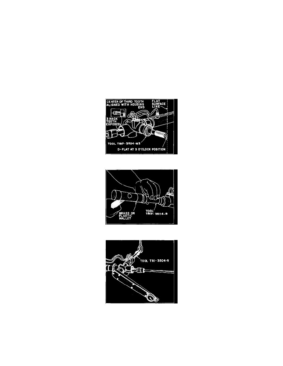
5.
Position rack in rack housing with three rack teeth protruding from left side of housing. Carefully observe rack while looking through valve
housing bore and center the visible rack tooth in the valve bore.
Fig. 38 Installing valve assembly. Escort, EXP, LN7, Lynx, Tempo & Topaz
Fig. 39 Installing input shaft bearing. Escort, EXP, LN7, Lynx, Tempo & Topaz
Fig. 31 Removing & installing pinion bearing locknut. Escort, EXP, LN7, Lynx, Tempo & Topaz