
Tempo L4-122 2.0L DSL (1984)
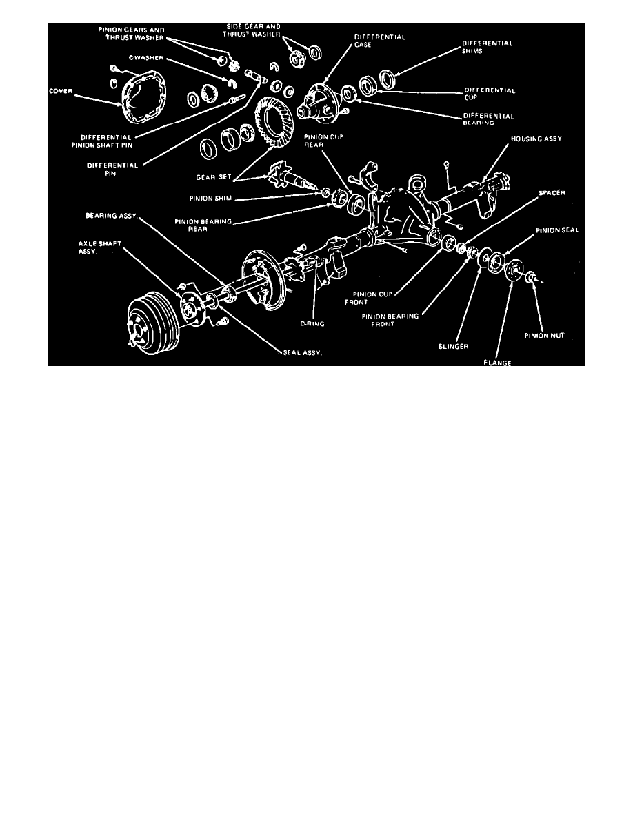
Fig. 2 Exploded view of 7-1/2, 8-1/2 & 8.8 inch ring gear rear axle
DIFFERENTIAL CASE ASSEMBLY
1.
Raise and support rear of vehicle, then loosen axle housing cover bolts and allow lubricant to drain into suitable container, Figs. 1 and 2.
2.
Remove axle housing cover, then proceed as follows:
a. Wipe excess lubricant from inside axle housing, then visually inspect parts for wear and/or damage.
b. Rotate gears and check for roughness, indicating damaged bearings or gears.
c. Install suitable dial indicator on axle housing cover flange, then check and record ring gear backface runout. Maximum backface runout is
.004 inch.
3.
Remove rear axles and propeller shaft. Refer to ``Rear Axle, Propeller Shaft & Brakes'' for procedures.
4.
Scribe reference marks on differential bearing bearing caps to be used during reassembly, then loosen bearing cap bolts. Observe and record
direction the arrows are facing on the bearing caps. During installation, then arrows must face in the same direction.
5.
Using suitable tool, pry differential case, bearing cups and shims out of housing until loose in the bearing caps. Remove bearing caps, then the
differential assembly. Mark side cups and shims came from for reference during reassembly.
DRIVE PINION
1.
Scribe reference mark between drive pinion and companion flange, then hold flange with suitable tool and remove pinion nut and pinion flange.
2.
Using suitable soft faced hammer, drive pinion out of front bearing cone and remove from rear of axle housing.
3.
Remove oil seal and front bearing cone and roller from pinion housing.
4.
Using suitable arbor press and adapters, remove rear pinion bearing.
5.
Using suitable micrometer, measure and record thickness of shim which is found under rear bearing cone.
6.
Remove pinion bearing cups from pinion housing with suitable brass drift. Install cups using suitable bearing cup installer. Cups are not properly
installed if a .015 feeler gauge can be installed between cup and bottom of bore at any point around the cup. If any bearing cups are replaced,
the respective bearing cone and roller must be replaced.