
Tempo FWD L4-140 2.3L HSC (1987)
Radiator Cooling Fan Motor: Pinpoint Tests
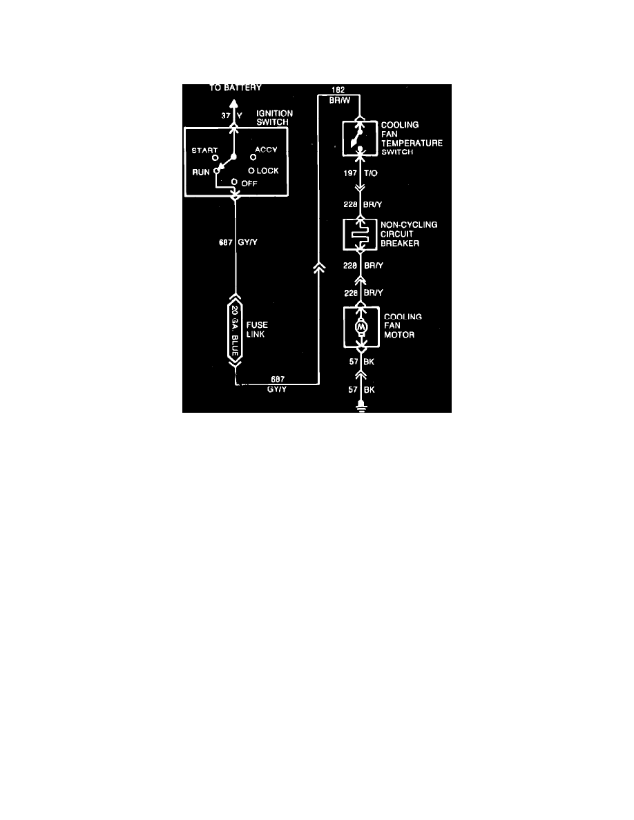
Type 36
Fig. 42 Electric engine cooling fan wiring diagram. Type 36
Refer to Fig. 42, during the following procedures.
1.
Disconnect fan motor electrical connector, then install a jumper from ground to B+ terminal. If motor does not operate, replace. If motor
operates, connect motor lead, then proceed to step 2.
2.
Disconnect electrical connector at cooling fan temperature switch, then check for voltage at circuit 197. If battery voltage is present, proceed to
step 3. If battery voltage is not present, check for open or short circuit in circuit 137 and or fusible link. Service as necessary, then check
operation of cooling fan.
3.
Jumper cooling fan temperature switch connector pins together and check that cooling fan motor is operating with ignition switch in ``On''
position. If motor is operating, replace temperature switch and recheck operation. If motor is not operating, leave jumper and proceed to step 4.
4.
Disconnect fan motor connector, then check for battery voltage at circuit 228. If battery voltage is present, proceed to step 5. If battery voltage is
not present, check for open in circuit 228. Service wiring between fan motor and cooling fan temperature switch. Connect temperature switch,
then recheck operation.
5.
Check ground circuit 57 for continuity. If continuity is present, replace cooling fan motor, connect cooling fan temperature switch connector, then
check operation. If continuity is not present, service open in circuit 57. Connect cooling fan motor connector and temperature switch, then
recheck fan operation.
Types 32 Through 35