| Removal and Installation Brake hose clamp Trolley jack Removal | | -
CAUTION:If brake fluid is spilt on the paintwork, the affected area must be immediately washed down with cold water. Remove the wheel hub. For additional information, refer to: (205-02B Wheel Hubs and Bearings - Full Floating Axle) Wheel Hub - VIN Plate Axle Code: A/B/C/D/G/M/P/X/Y (Removal and Installation), Wheel Hub - VIN Plate Axle Code: E/F/H/J/K/L/R (Removal and Installation). | | | -
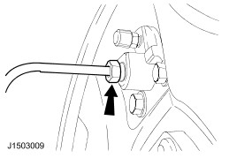
Detach the brake hose retaining bracket from the axle housing. | | | -
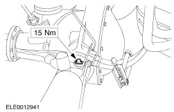
Remove the axle housing vent. | | | -
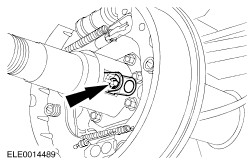
CAUTION:Cap the brake tubes to prevent fluid loss or dirt ingress. Disconnect the brake tubes from the wheel cylinders. | | | -
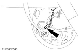
Detach the rear wheel speed sensors from the brake backing plates. | | | -
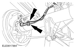
Remove the rear wheel speed sensor retaining brackets from the axle tubes. | | | -
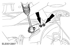
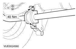
Detach the shock absorbers from the axle housing. | | | -
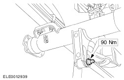
Detach the stabilizer bar from the axle housing and secure it to the chassis (if equipped). | | | -
Detach the brake tubes and the wheel speed sensor wiring harness from the retaining clips on the axle housing. | | | -
NOTE:Mark the position of the driveshaft flange in relation to the drive pinion flange. Detach the driveshaft from the drive pinion flange and position it to one side. | | | -
WARNING:Driveshafts without a sliding joint protective boot must have the rear section of the driveshaft removed to prevent accidental seperation of the sliding joint. Failure to follow this instruction may result in personal injury. Remove the rear section of the driveshaft if necessary. | | | -
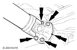
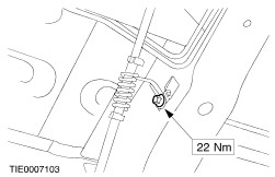
Detach the brake load sensor proportioning valve from the axle housing. - Discard the bolts and nuts.
| | | -
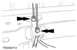
Detach the parking brake right-hand rear cable from the chassis. | | | -
Detach the parking brake left-hand rear cable from the chassis. | | | -
Detach the parking brake rear cables from the retaining bracket. | | | -
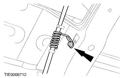
Detach the parking brake intermediate cable from the equalizer. - Remove the adjustment nut.
- Detach the cable.
| | | -
Detach the brake backing plate assemblies from the axle housing. - Remove the protective cap.
| | | -
Secure the brake backing plate assemblies to the rear springs. | | | -
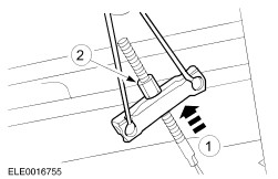
Remove the spring U-bolts. | | | -
Remove the axle assembly. | Installation | | -
Using a suitable trolley jack, locate the axle assembly under the vehicle. | | | -
NOTE:Final tightening of the rear suspension components should be carried out when the vehicle weight is on the road wheels. NOTE:Install new spring U-bolt nuts. NOTE:Do not fully tighten the spring U-bolt nuts at this stage. Install the spring U-bolts. - Locate the spring to the rear axle assembly.
- Install the guide plates and U-bolts.
- Install the nuts.
| | | -
Attach the stabilizer bar to the axle housing (if equipped). | | | -
Attach the shock absorbers to the axle housing. | | | -
Attach the brake backing plate assemblies to the axle housing. - Install the protective cap.
| | | -
Attach the parking brake intermediate cable to the equalizer. - Attach the cable.
- Install the adjustment nut.
| | | -
Attach the parking brake rear cables to the retaining bracket. | | | -
Attach the parking brake left-hand rear cable to the chassis. | | | -
Attach the parking brake right-hand rear cable to the chassis. | | | -
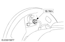
CAUTION:Install new bolts and nuts. Attach the brake load sensor proportioning valve to the axle housing. | | | -
NOTE:Make sure that the arrows are aligned. Install the rear section of the driveshaft if necessary. | | | -
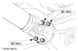
NOTE:Align the mark on the driveshaft flange with the mark on the drive pinion flange. Attach the driveshaft to the drive pinion flange. | | | -
Install the rear wheel speed sensor retaining brackets to the axle tubes. | | | -
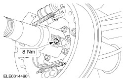
Attach the rear wheel speed sensors to the brake backing plates. | | | -
Connect the brake tubes to the wheel cylinders. | | | -
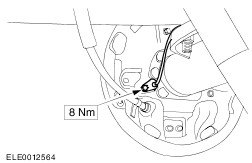
Attach the brake hose retaining bracket to the axle housing. | | | -
Install the axle housing vent. | | | -
Install the wheel hub. For additional information, refer to: (205-02B Wheel Hubs and Bearings - Full Floating Axle) Wheel Hub - VIN Plate Axle Code: A/B/C/D/G/M/P/X/Y (Removal and Installation), Wheel Hub - VIN Plate Axle Code: E/F/H/J/K/L/R (Removal and Installation). | | | -
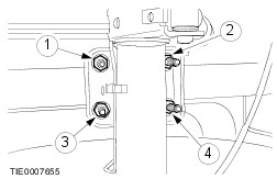
Tighten the spring U-bolt nuts in the sequence shown in seven stages. - Stage 1: Tighten nuts 1 through 4 to 25 Nm.
- Stage 2: Tighten nuts 1 through 4 to 50 Nm.
- Stage 3: Tighten nuts 1 through 4 to 75 Nm.
- Stage 4: Tighten nuts 1 through 4 to 100 Nm.
- Stage 5: Tighten nuts 1 through 4 to 125 Nm.
- Stage 6: Tighten nuts 1 through 4 to 150 Nm.
- Stage 7: Tighten nuts 1 through 4 to 175 Nm.
| | | -
Adjust the parking brake. For additional information, refer to: Parking Brake Cable Adjustment (206-05A Parking Brake and Actuation, General Procedures), Parking Brake Cable Adjustment (206-05B Parking Brake and Actuation - Vehicles With: Parking Brake Assist, General Procedures). | | | -
Bleed the brake system.
For additional information, refer to: Brake System Bleeding (206-00 Brake System - General Information, General Procedures).
| | |