| Removal and Installation Removal All vehicles WARNING:Always wear safety glasses when working on an air bag equipped vehicle and when handling an air bag module. Failure to following this instruction may result in person injury. | | -
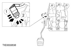
Detach the brake pedal position (BPP) switch from the brake pedal bracket. | | | -
Detach the turn signal lamp relay from the brake pedal bracket. | | | -
Detach the brake booster actuating rod from the brake pedal. - Remove the clip.
- Remove the pin.
| | | -
Detach the clutch pedal position switch from the brake pedal bracket (if equipped). | Right-hand drive vehicles | | -
Detach the clutch master cylinder actuating rod from the clutch pedal. | | | -
Detach the clutch master cylinder from the bulkhead. - Rotate it clockwise through 90 degrees.
| | | -
NOTE:Make sure the road wheels are in the straight ahead position. Centralize the steering and lock it in position. | | | -
Remove the steering column upper shroud. - Using a thin bladed screwdriver, release the two clips (one each side).
- Remove the shroud.
| | | -
Remove the steering column lower shroud. | | | -
Detach the steering column and position it to one side. - Discard the retaining nuts.
| | | -
Remove the brake pedal and bracket (brake pedal shown removed for clarity). | Left-hand drive vehicles | | -
Remove the brake pedal and bracket (brake pedal shown removed for clarity). | Installation Left-hand drive vehicles | | -
Install the brake pedal and bracket (brake pedal shown removed for clarity). | Right-hand drive vehicles | | -
Install the brake pedal and bracket (brake pedal shown removed for clarity). | | | -
WARNING:Install new steering column locknuts. Failure to follow this instruction may result in personal injury. Attach the steering column. | | | -
Install the steering column lower shroud. | | | -
Install the steering column upper shroud. | | | -
Attach the clutch master cylinder to the bulkhead. - Rotate it counterclockwise through 90 degrees.
| | | -
Attach the clutch master cylinder actuating rod to the clutch pedal. | All vehicles | | -
CAUTION:The clutch pedal position switch is automatically adjusted during installation. Attach the clutch pedal position switch to the brake pedal bracket (if equipped). - Insert the clutch pedal position switch into the pedal bracket hole and push down to depress the switch plunger.
- Turn the switch clockwise to lock it in position.
| | | -
Attach the brake booster actuating rod to the brake pedal. - Install the pin.
- Install the clip.
| | | -
Attach the turn signal lamp relay to the brake pedal bracket. | | | -
CAUTION:The brake pedal position switch (BPP) is automatically adjusted during installation. Do not move the brake pedal. Attach the BPP switch to the brake pedal bracket. - Insert the BPP switch into the pedal bracket hole and push down to depress the switch plunger.
- Turn the switch clockwise to lock in position.
| |