| Removal Special Tool(s) | | Remover/Installer, Hose Clamp 303-397 (24-003) | General Equipment Engine hoist Trolley jack Two M10 x 60 mm locating studs Axle stands Removal WARNING:Do not smoke or carry lighted tobacco or open flame of any type when working on or near any fuel related components. Highly flammable mixtures are always present and may ignite. Failure to follow these instructions may result in personal injury. All except vehicles with LPG fuel system | | -
Release the fuel system pressure.
For additional information, refer to: Fuel System Pressure Release - 2.3L DOHC-16V (310-00A Fuel System - General Information, General Procedures).
| Vehicles with LPG fuel system | | -
Evacuate the fuel line.
For additional information, refer to: Fuel Line Evacuation Using Recovery Equipment (310-00B Fuel System - General Information - Liquified Petroleum Gas (LPG), General Procedures).
| All vehicles | | -
Drain the cooling system.
For additional information, refer to: Cooling System Draining, Filling and Bleeding (303-03 Engine Cooling, General Procedures).
| | | -
Remove the accessory drive belt.
For additional information, refer to: Accessory Drive Belt - 2.3L DOHC-16V (303-05 Accessory Drive, Removal and Installation).
| | | -
Remove the radiator grille opening panel.
For additional information, refer to: Radiator Grille Opening Panel (501-02 Front End Body Panels, Removal and Installation).
| | | -
NOTE:Select neutral prior to removing the gearshift lever. Remove the gearshift lever. - Pull up the boot.
- Pull the plunger and remove the gearshift lever.
- Remove the insulator.
| | | -
Remove the gearshift lever insulation pad. | | | -
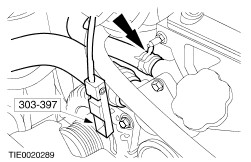
Using the special tool, disconnect the coolant hoses from the thermostat housing. | | | -
Remove the radiator.
For additional information, refer to: Radiator - 2.3L DOHC-16V (303-03 Engine Cooling, Removal and Installation).
| | | -
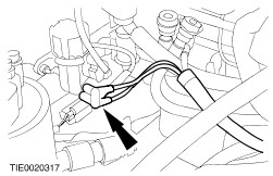
Using the special tool, disconnect the coolant hose from the water pump. | Vehicles with air conditioning | | -
Detach the condenser core and position it to one side. | Vehicles with LPG fuel system | | -
Disconnect the LPG fuel injection supply manifold hoses. | Vehicles with LPG fuel system | | -
Remove the LPG fuel injection supply manifold. | All vehicles | | -
Remove the air cleaner outlet pipe. | | | -
Remove the power steering pump pulley. - Use a 9 mm Allen key to prevent the power steering pump pulley from rotating.
| | | -
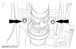
Remove the power steering pump rear retaining bolts. | | | -
Detach the power steering pump from the mounting bracket and position it to one side. | | | -
Disconnect the power steering pressure (PSP) switch electrical connector. | | | -
Disconnect the lower coolant hose from the heater core. | All except vehicles with LPG fuel system | | -
Disconnect the engine wiring harness electrical connector. | | | -
Detach the engine wiring harness electrical connector from the retaining bracket. | Vehicles with LPG fuel system | | -
Disconnect the engine wiring harness electrical connector. | | | -
Detach the engine wiring harness electrical connectors from the retaining bracket. | All vehicles | | -
Remove the jump start point cover. | | | -
Disconnect the battery to starter motor solenoid cable from the jump start point. | | | -
Disconnect the fuel supply and return lines.
For additional information, refer to: Quick Release Coupling (310-00A Fuel System - General Information, General Procedures).
| | | -
Disconnect the engine ground cable from the side member. | | | -
Disconnect the engine ground cable from the cylinder head. | | | -
Detach the accelerator cable from the throttle body. | | | -
Detach the accelerator cable bracket from the throttle body and position it to one side. | | | -
Disconnect the brake booster vacuum hose from the intake manifold. | | | -
Disconnect the vapor line from the intake manifold. | | | -
Disconnect the vapor line from the evaporative emission canister. | | | -
Disconnect the positive crankcase ventilation (PCV) hose from the valve cover. | | | -
Disconnect the evaporative emission canister purge valve electrical connector. | | | -
Disconnect the exhaust gas recirculation (EGR) vacuum regulator solenoid vacuum lines. | | | -
Remove the catalytic converter.
For additional information, refer to: Catalytic Converter - 2.3L DOHC-16V (309-00 Exhaust System, Removal and Installation).
| | | -
Remove the driveshaft front center bearing retaining bolts. | Vehicles built up to 10/2001 | | -
NOTE:Mark the position of the driveshaft flange in relation to the transmission output shaft flange. Detach the driveshaft from the transmission output shaft flange and position it to one side. | Vehicles built 10/2001 onwards | | -
NOTE:Mark the position of the driveshaft flange in relation to the transmission output shaft flange. Detach the driveshaft from the transmission output shaft flange and position it to one side. | All vehicles | | -
Detach the clutch slave cylinder from the transmission. | | | -
Remove the transmission support insulator to front axle crossmember bolts. | Vehicles with air conditioning | | -
Disconnect the A/C compressor clutch electrical connector. | | | -
Detach the A/C compressor wiring harness from the A/C compressor. | | | -
Disconnect the high-pressure cutoff switch electrical connector. | | | -
Remove the A/C compressor retaining bolts. | | | -
Detach the refrigerant line support bracket from the A/C compressor. | | | -
CAUTION:Support the A/C compressor before removing the retaining bolts and secure it to prevent load being placed on the refrigerant lines. Detach the A/C compressor and position to one side. | All vehicles | | -
Using a suitable trolley jack, support the engine crossmember. | | | -
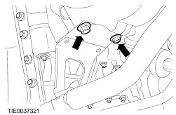
Remove the engine crossmember retaining bolts. | | | -
Using suitable axle stands, support the engine crossmember. | | | -
Remove the engine crossmember support brackets. | | | -
Detach the engine wiring harness from the engine crossmember. | | | -
Using a suitable trolley jack, support the transmission. | | | -
CAUTION:To avoid damage to the engine wiring harness, make sure the vehicle is only pushed backwards sufficiently to gain access to the starter motor solenoid. With the aid of another technician, push the vehicle backwards to gain sufficient access to the engine rear lifting eye. | | | -
Remove the engine support insulator retaining nuts. | | | -
Using a suitable engine hoist, with the aid of another technician, lift the engine and transmission assembly over the towing eye and push the vehicle backwards. | | | -
Disconnect the jump start point to starter motor solenoid cable and the ignition switch to starter motor solenoid cable from the starter motor. | | | -
Disconnect the starter motor ground cable and remove the starter motor. | | | -
Remove two transmission retaining bolts and install the M10 x 60 mm locating studs. | | | -
Remove the transmission right-hand retaining bolts. | | | -
Remove the transmission left-hand retaining bolts. | | | -
CAUTION:Do not tilt the transmission during removal. Failure to follow this instruction may result in damage to the crankshaft pilot bearing. Remove the transmission from the engine. | |