| Diagnosis and Testing Worldwide Diagnostic System (WDS) Principles of Operation The instrument cluster carries out a display prove-out to verify that all warning/indicator lamps and monitored systems are operating correctly. When the ignition switch is turned to the ON position with the engine OFF, the following indicators will illuminate: - Oil service lamp
- Charge system warning indicator.
- Anti-lock brake system (ABS) warning indicator.
- Air bag indicator.
- Glow plug indicator/engine check lamp (diesel only).
Gauge Indication Systems The gauge indication systems use magnetic gauges mounted in the instrument cluster. No adjustment, calibration, or maintenance is required for any gauges. Fuel Sending Unit The fuel sending unit is a variable resistor controlled by the action of a float arm. When the fuel level is low, resistance in the unit is low. When the fuel level is high, the resistance is high. Water Temperature Indicator Sender Unit When the engine temperature is low, the resistance of the water temperature indicator sender unit is high, thus restricting the flow of current through the gauge and moving the pointer only a short distance. As the temperature of the coolant increases, the resistance decreases, allowing more current to flow through the gauge and resulting in a corresponding movement of the pointer. For vehicles with diesel engines the temperature gauge receives a pulse width modulation (PWM) signal from the powertrain control module (PCM). Oil Pressure Indicator Sender Unit The oil pressure indicator sender unit consists of a diaphragm and contact points. The contact points are open with oil pressure causing the oil pressure indicator to extinguish. With no oil pressure, the contacts close and the low oil pressure indicator illuminates. Charge System Warning Indicator A red charge indicator is located in the instrument cluster. This indicator illuminates when there is low or no generator output. When the ignition switch contacts are closed, battery current flows through the charge indicator and the parallel resistor (390 ohms) to the voltage indicator, and the indicator comes on. When the generator builds up enough voltage to energize a circuit in the voltage regulator, the indicator turns off. Speedometer On vehicles equipped with tachograph, the speedometer receives the vehicle speed output (VSO) signal from a speed sensor in the transmission. On vehicles without a tachograph, the speedometer receives the vehicle speed signal directly from the PCM. Odometer A million-mile tamper-resistant odometer is standard. The odometer can be reset when installing a new speedometer. Trip Odometer The trip odometer indicates how many miles the vehicle has been driven since the last reset. Tachometer All vehicles can be equipped with a tachometer as an option. Diesel vehicles are equipped with a 4500–rpm tachometer. The tachometer receives a signal from the PCM. Warning Indicators Brake System All vehicles use a brake system warning indicator in the instrument cluster to warn of system malfunctions. The red brake warning light (BRAKE) is used to indicate a low fluid level, brake malfunction. The brake fluid level switch is located in the brake fluid reservoir. The yellow brake warning indicator is used to indicate a malfunction or deactivation of the anti-lock brake system (ABS). It illuminates when triggered by the ABS control module and stays illuminated as long as the malfunction remains in the system. Service Indicator Lamp The service indicator lamp will illuminate when a service is required. To extinguish the service indicator lamp following a service, turn the ignition switch to position II, press the brake and accelerator pedals together for 15 seconds. The service indicator lamp will flash to confirm the lamp has been reset. Release the pedals and turn the ignition switch to OFF. Low Fuel When the fuel level drops to a predetermined level, approximately four to eight liters (one to two gallons), the low fuel warning indicator will illuminate. High Beam This indicator is illuminated when the high beams are ON. Water-in-Fuel (Diesel Only) The WATER-IN-FUEL indicator will illuminate when 100cc (0.2 pints) of water has accumulated in the fuel filter/water separator. The WATER-IN-FUEL indicator will prove out when the ignition switch is in the START position. Glow Plug Indicator/Engine Check Lamp (Diesel Only) The glow plug indicator will illuminate when the ignition switch is in the ON position with the engine OFF while the glow plugs are heating. The indicator also acts as an engine check lamp which will flash continuously when a hard diagnostic trouble code (DTC) is detected by the powertrain control module (PCM). CHECK ENGINE Warning Indicator (Petrol Only) The CHECK ENGINE warning indicator is illuminated when a DTC is sensed in the closed loop by the PCM. Inspection and Verification - Verify the customer concern.
- Visually inspect for obvious signs of mechanical or electrical damage.
Visual Inspection Chart | Mechanical | Electrical | - Engine oil filter
- Oil pump
- Engine oil level
- Oil pressure switch
- Coolant temperature gauge
- Engine coolant level
- Coolant thermostat
- Fuel gauge
- Liquified Petroleum Gas (LPG) fuel gauge
- Tachometer
| - Fuse(s)
- Bulb(s)
- Wiring harness
- Electrical connector(s)
- Instrument cluster
- Instrument cluster printed circuit
| - Verify the following systems are working correctly:
- Charging.
- Fuel delivery.
- Cooling.
- Turn signals.
- Headlamps.
If a particular system(s) is not working correctly, refer to the appropriate section of the workshop manual. - If an obvious cause for an observed or reported concern is found, correct the cause before proceeding to the next step.
- If the cause is not visually evident, verify the symptom and refer to the Symptom Chart.
Symptom Chart Symptom Chart | Symptom | Possible Sources | Action | | A gauge is inoperative — all gauges | * Fuse. * Circuit. * Printed circuit. * Instrument cluster connectors. | * | | Incorrect fuel gauge indication | * Fuel sender. * Circuit. * Fuel tank. * Fuel gauge and instrument cluster gauge amplifier. * Instrument cluster printed circuit. * Fuel pump module. | * | | Incorrect LPG fuel gauge indication - Vehicles with LPG fuel system | * LPG level sensor. * Circuit. * LPG control module. * PCM * Instrument cluster. | * | | The LPG select indicator is inoperative - Vehicles with LPG fuel system | * Circuit. * LPG control module. * PCM * Instrument cluster. * Fuel selection switch | * | | The low fuel warning indicator is never/always on | * Fuse. * Circuit. * Instrument cluster printed circuit. * Indicator bulb. | * | | Incorrect temperature gauge indication | * Circuit. * Coolant temperature sender. * Instrument cluster printed circuit. * Powertrain control module (PCM). | * | | The speedometer/odometer is inoperative | * Fuse(s). * Circuit. * Speedometer. * Instrument cluster printed circuit. * Powertrain control module (PCM). | * | | The tachometer is inoperative | * Circuit. * Tachometer. * Instrument cluster printed circuit. * Powertrain control module (PCM). | * | | Inaccurate speedometer reading — odometer functions correctly | * Instrument cluster printed circuit. * Tires. | * | | The brake warning indicator is never/always on – yellow ABS warning indicator | * ABS warning indicator bulb. * Circuit. * Instrument cluster printed circuit. * ABS module. | * | | The brake warning indicator is never/always on – red brake warning indicator | * Fuse. * Brake warning indicator bulb. * Circuit. * Instrument cluster printed circuit. * ABS module. * Brake fluid level switch. * Parking brake switch. | * | | CHECK ENGINE indicator is inoperative/always on | * CHECK ENGINE indicator bulb. * Circuit. * Instrument cluster printed circuit. | * | | The charge system warning indicator is never/always on | * Fuse. * Charging system. * Charge system warning indicator bulb. * Circuit. * Instrument cluster printed circuit. | * | | The air bag indicator is inoperative/always on | * Air bag indicator bulb. * Circuit. * Instrument cluster printed circuit. * Air bag diagnostic monitor. | * | | The high beam indicator is inoperative | * High beam indicator bulb. * Circuit. * Instrument cluster printed circuit. | * | | The LH turn indicator is inoperative | * LH turn indicator bulb. * Circuit. * Instrument cluster printed circuit. | * | | The RH turn indicator is inoperative | * RH turn indicator bulb. * Circuit. * Instrument cluster printed circuit. | * | | The Glow Plug indicator is inoperative/always on–diesel only | * Fuse(s). * Circuit. * Powertrain control module (PCM). * Relay. | * | | The Water in Fuel indicator is inoperative/always on–diesel only | * Water-in-Fuel indicator bulb. * Circuit. * Water-in-fuel switch. * Instrument cluster printed circuit. | * | | The Oil Pressure warning indicator is inoperative/always on | * Oil pressure warning indicator. * Instrument cluster printed circuit. * Circuit. * Oil pressure switch. | * | Pinpoint Tests NOTE:Use a digital multimeter for all electrical measurements. | PINPOINT TEST A : A GAUGE IS INOPERATIVE – ALL GAUGES | | TEST CONDITIONS | DETAILS/RESULTS/ACTIONS | | A1: VERIFY WARNING INDICATOR PROVE OUT | | | 1 Ignition switch in position II. | | | 2 Observe the instrument cluster warning indicators. | | | 3 Ignition switch in position III. | | | Do the CHECK ENGINE, charge system, oil pressure, brake, or ABS indicators prove out? Yes No | | A2: CHECK THE PRINTED CIRCUIT AND VERIFY CONNECTOR SEATING | | | 1 Check the instrument cluster printed circuit for damage and verify the instrument cluster is connected correctly. | | | Is the instrument cluster printed circuit OK and are the instrument cluster connectors connected correctly? Yes No REFER to: Instrument Cluster (413-01 Instrument Cluster, Removal and Installation). TEST the system for normal operation. | | A3: CHECK CIRCUIT(S) 15-GA6 (GN/YE), 15-LK29 (BN/BU) FOR POWER | | | 1 Disconnect Instrument Cluster C220a. | | | 2 Ignition switch in position II. | | | 3 Measure the voltage between the instrument cluster C220a pin 1, circuit 15-GA6 (GN/YE), harness side and ground; and between the instrument cluster C220a pin 9, circuit 15-LK27 (BN/LB), harness side and ground. | | | Are the voltages greater than 10 volts? Yes No REPAIR the circuit(s) in question. TEST the system for normal operation. | | A4: CHECK GROUND CIRCUIT 31-GG14B (BK) FOR OPEN | | | 1 Measure the resistance between the instrument cluster C220a pin 13, circuit 31-GG14B (BK), harness side and ground. | | | Is the resistance less than 5 ohms? Yes No REPAIR the circuit. TEST the system for normal operation. | | A5: CHECK GROUND CIRCUIT 31-GG14B (BK) FOR SHORT TO POWER | | | 1 Measure the voltage between the instrument cluster C220a pin 13, circuit 31-GG14B (BK), harness side and ground. | | | Is there voltage present? Yes REPAIR the circuit. TEST the system for normal operation. No REFER to: Instrument Cluster (413-01 Instrument Cluster, Removal and Installation). TEST the system for normal operation. | | PINPOINT TEST B : INCORRECT FUEL GAUGE INDICATION | | TEST CONDITIONS | DETAILS/RESULTS/ACTIONS | | B1: CHECK FUEL GAUGE | | | 1 Carry out the Fuel Gauge Component Test. Refer to WDS. | | | Does the fuel gauge operate correctly? Yes No | | B2: INSPECT THE FUEL TANK | | | 1 Ignition switch in position 0. | | | 2 Visually inspect the fuel tank for any damage or deformation. | | | Is the fuel tank OK? Yes No INSTALL a new fuel tank.
REFER to: Fuel Tank (310-01A Fuel Tank and Lines, Removal and Installation).
TEST the system for normal operation. | | B3: INSPECT THE FUEL PUMP MODULE | | | 1 Inspect the fuel pump module, wiring, float, and float rod for damage or obstruction. | | | Is the fuel pump module OK? Yes No Install a new fuel pump module.
REFER to: Fuel Tank (310-01A Fuel Tank and Lines, Removal and Installation).
TEST the system for normal operation. | | B4: CHECK CIRCUIT 31-GA7 (BK) FOR OPEN | | | 1 Ignition switch in position 0. | | | 2 Disconnect Fuel Level Sensor C434. | | | 3 Measure the resistance between the fuel level sensor and pump C434 pin 4, circuit 31-GA7 (BK), harness side and ground. | | | Is the resistance less than 5 ohms? Yes No REPAIR the circuit. TEST the system for normal operation. | | B5: CHECK CIRCUIT 8-GA6 (WH) FOR OPEN OR SHORT TO GROUND | | | 1 Disconnect Instrument Cluster C220b. | | | 2 Measure the resistance between the instrument cluster C220b pin 7, circuit 8-GA6 (WH), harness side and the fuel level sensor C434 pin 2, circuit 8-GA6 (WH), harness side; and between the instrument cluster C220b pin 7, circuit 8-GA6 (WH), harness side and ground. | | | Is the resistance less than 5 ohms between the instrument cluster and the fuel level sensor, and greater than 10,000 ohms between the instrument cluster and ground? Yes No REPAIR the circuit. TEST the system for normal operation. | | B6: CHECK THE INSTRUMENT CLUSTER PRINTED CIRCUIT AND VERIFY CONNECTOR SEATING | | | 1 Check the instrument cluster printed circuit for damage and verify the instrument cluster is connected correctly. | | | Is the instrument cluster printed circuit OK and are the instrument cluster connectors connected correctly? Yes INSTALL a new fuel gauge and instrument cluster gauge amplifier. TEST the system for normal operation. No REFER to: Instrument Cluster (413-01 Instrument Cluster, Removal and Installation). TEST the system for normal operation. | | PINPOINT TEST C : INCORRECT LPG FUEL GAUGE INDICATION - VEHICLES WITH LPG FUEL SYSTEM | | TEST CONDITIONS | DETAILS/RESULTS/ACTIONS | | C1: CHECK FUEL GAUGE | NOTE:Make sure the LPG selection switch is selected in LPG. | | | 1 Carry out the Fuel Gauge Component Test. Refer to WDS. | | | Does the LPG fuel gauge operate correctly? Yes No | | C2: CHECK FUEL GAUGE | | | 1 De-select the LPG fuel gauge by operating the fuel selection switch. | | | 2 Check the petrol fuel gauge for correct operation. | | | Does the petrol fuel gauge operate correctly? Yes No INSTALL a new instrument cluster.
REFER to: Instrument Cluster (413-01 Instrument Cluster, Removal and Installation).
TEST the system for normal operation. | | C3: INSPECT THE FUEL TANK | | | 1 Ignition switch in position 0. | | | 2 Visually inspect the fuel tank for any damage or deformation. | | | Is the fuel tank OK? Yes No INSTALL a new fuel tank.
REFER to: Fuel Tank (310-01B Fuel Tank and Lines - Liquified Petroleum Gas (LPG), Removal and Installation).
TEST the system for normal operation. | | C4: CHECK CIRCUIT 8-GA10 (WH/GN) FOR POWER | | | 1 Disconnect LPG level sensor C7011. | | | 2 Measure the voltage between the LPG fuel tank C7011 pin 1, circuit 8-GA10 (WH/GN), harness side and ground. | | | Is the voltage 5 volts? Yes No | | C5: CHECK CIRCUIT 14S-GA10 (VT/BK) FOR OPEN | | | 1 Measure the resistance between the LPG fuel tank C7011 pin 3, circuit 14S-GA10 (VT/BK), harness side and ground. | | | Is the resistance less than 5 ohms? Yes No REPAIR the circuit. TEST the system for normal operation. | | C6: CHECK THE FUEL LEVEL SENSOR GAUGE FOR CORRECT OPERATION | | | 1 Remove the LPG fuel level sensor gauge.
REFER to: Fuel Tank (310-01B Fuel Tank and Lines - Liquified Petroleum Gas (LPG), Removal and Installation).
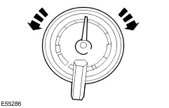
| | | NOTE:Place the magnet underneath the fuel level sensor gauge. 2 Using a suitable magnet, check the fuel level sensor gauge for movement by twisting the magnet clockwise and counterclockwise. | | | Does the fuel level sensor gauge move freely? Yes INSTALL a new fuel level sensor.
REFER to: Fuel Tank (310-01B Fuel Tank and Lines - Liquified Petroleum Gas (LPG), Removal and Installation).
TEST the system for normal operation. No INSTALL an new fuel level sensor gauge. TEST the system for normal operation. | | C7: CHECK CIRCUIT 8-GA10 (WH/GN) FOR OPEN | | | 1 Disconnect Instrument Cluster C7003. | | | 2 Measure the resistance between the LPG fuel tank C7011 pin 1, circuit 8-GA10 (WH/GN), harness side and the instrument cluster C7003, pin 3, circuit 8-GA10 (WH/GN), harness side. | | | Is the resistance less than 5 ohms? Yes INSTALL a new instrument cluster.
REFER to: Instrument Cluster (413-01 Instrument Cluster, Removal and Installation).
TEST the system for normal operation. No REPAIR the circuit. TEST the system for normal operation. | | PINPOINT TEST D : THE LPG SELECT INDICATOR IS INOPERATIVE - VEHICLES WITH LPG FUEL SYSTEM | | TEST CONDITIONS | DETAILS/RESULTS/ACTIONS | | D1: CHECK THE FUEL SELECTION SWITCH FOR CORRECT OPERATION | | | 1 Start the engine and allow it to idle until it reaches normal operation temperature. | | | 2 Select the LPG fuel gauge by operating the fuel selection switch. | | | Does the LPG selection switch illuminate? Yes No | | D2: CHECK THE FUEL SELECTION SWITCH TO INSTRUMENT CLUSTER CIRCUIT (BK) FOR POWER | | | 1 Ignition switch in position 0. | | | 2 Disconnect Instrument Cluster C7003. | | | 3 Ignition switch in position III. | | | 4 Select the LPG fuel gauge by operating the fuel selection switch. | | | 5 Measure the voltage between the instrument cluster C7003, pin 5, circuit (BK), harness side and ground. | | | Is the voltage greater than 10 volts? Yes INSTALL a new instrument cluster.
REFER to: Instrument Cluster (413-01 Instrument Cluster, Removal and Installation).
TEST the system for normal operation. No | | D3: CHECK THE FUEL SELECTION SWITCH TO INSTRUMENT CLUSTER CIRCUIT (BK) FOR POWER | | | 1 Disconnect Fuel Selection Switch C7000. | | | 2 Disconnect Instrument Cluster C7003. | | | 3 Measure the resistance between the instrument cluster C7003, pin 5, circuit (BK), harness side and the fuel selection switch, C7002 pin 8, circuit (BK), harness side. | | | Is the resistance less than 5 ohms? Yes INSTALL an new fuel selection switch. TEST the system for normal operation. No REPAIR the circuit. TEST the system for normal operation. | | D4: CHECK THE FUEL SELECTION SWITCH FOR POWER | | | 1 Disconnect Fuel Selection Switch C7000. | | | 2 Ignition switch in position I. | | | 3 Measure the voltage between the fuel selection switch, C7002 pin 2 circuit (BK), harness side and ground. | | | Is the voltage greater than 10 volts? Yes No REPAIR the circuit. TEST the system for normal operation. | | D5: CHECK THE FUEL SELECTION SWITCH FOR GROUND | | | 1 Ignition switch in position 0. | | | 2 Measure the resistance between the fuel selection switch, C7002 pin 4 circuit (BN/BK), harness side. | | | Is the resistance less than 5 ohms? Yes INSTALL an new fuel selection switch. TEST the system for normal operation. No REPAIR the circuit. TEST the system for normal operation. | | PINPOINT TEST E : THE LOW FUEL WARNING INDICATOR IS NEVER/ALWAYS ON | | TEST CONDITIONS | DETAILS/RESULTS/ACTIONS | | E1: CHECK THE FUEL GAUGE | | | 1 Ignition switch in position II. | | | 2 Check the fuel gauge. | | | Does the fuel gauge operate correctly? Yes No | | E2: CHECK THE INSTRUMENT CLUSTER PRINTED CIRCUIT | | | 1 Ignition switch in position 0. | | | 2 Disconnect Instrument Cluster C220b. | | | 3 Inspect the instrument cluster printed circuit for damage. | | | Is the instrument cluster printed circuit damaged? Yes REFER to: Instrument Cluster (413-01 Instrument Cluster, Removal and Installation). TEST the system for normal operation. No CHECK the fuel warning indicator bulb. Install a new bulb as necessary. TEST the system for normal operation. | | PINPOINT TEST F : INCORRECT TEMPERATURE GAUGE INDICATION | | TEST CONDITIONS | DETAILS/RESULTS/ACTIONS | | F1: CHECK THE GAUGE OPERATION–COLD | NOTE:For correct operation of the temperature gauge, make sure the engine coolant is at the correct level and that the connector is securely connected to the coolant temperature sender. | | | 1 Disconnect Powertrain Control Module (PCM) C175. | | | 2 Ignition switch in position II. | | | 3 Observe the temperature gauge | | | Does the temperature gauge read in the cold band? Yes No | | F2: CHECK THE GAUGE OPERATION–HOT | NOTE:For correct operation of the temperature gauge, make sure the engine coolant is at the correct level and that the connector is securely connected to the coolant temperature sender. | | | 1 Ignition switch in position II. | | | 2 Connect a fused (10A) jumper between the PCM C175 pin 46, circuit 91S-RE27 (BN/YE), harness side and ground. | | | Does the temperature gauge read in the hot band? Yes REFER to WDS/FDS 2000. No | | F3: CHECK CIRCUIT 91S-RE27 (BN/YE) FOR OPEN OR SHORT TO GROUND | | | 1 Disconnect Instrument Cluster C220a. | | | 2 Ignition switch in position 0. | | | 3 Measure the resistance between the instrument cluster C220a pin 6, circuit 91S-RE27 (BN/YE), harness side and the PCM C175 pin 46, circuit 91S-RE27 (BN/YE), harness side; and between the instrument cluster C220a pin 6, circuit 91S-RE27 (BN/YE), harness side and ground. | | | Is the resistance less than 5 ohms between the instrument cluster and the PCM; and greater than 10,000 ohms between the instrument cluster and ground? Yes No REPAIR the circuit. TEST the system for normal operation. | | F4: CHECK THE CIRCUIT 15-GA6 (GN/YE) FOR POWER | | | 1 Measure the voltage between the instrument cluster C220a pin 1, circuit 15-GA6 (GN/YE), harness side and ground. | | | Is the voltage greater than 10 volts? Yes No REPAIR the circuit. TEST the system for normal operation. | | F5: CHECK THE PRINTED CIRCUIT AND VERIFY CONNECTOR SEATING | | | 1 Check the instrument cluster printed circuit for damage and verify the instrument cluster is connected correctly. | | | Is the instrument cluster printed circuit OK and are the instrument cluster connectors connected correctly? Yes INSTALL a new engine coolant temperature gauge. TEST the system for normal operation. No REFER to: Instrument Cluster (413-01 Instrument Cluster, Removal and Installation). TEST the system for normal operation. | | PINPOINT TEST G : THE SPEEDOMETER/ODOMETER IS INOPERATIVE | | TEST CONDITIONS | DETAILS/RESULTS/ACTIONS | | G1: CHECK THE SPEEDOMETER SIGNAL USING A WDS/FDS 2000 AT 48KM/H (30 MPH) | NOTE:Vehicle must be traveling at a steady speed while carrying out this test. | NOTE:Only carry out test step E1 if speed limits do not allow teststep E2 to be carried out. | | | 1 Connect the diagnostic tool. | | | 2 Enter the following diagnostic mode: . 3 Monitor the PCM VSS PID in the powertrain control module mode while driving the vehicle at 48 km/h (30 mph). | | | Does the scan tool read 45-47 km/h (28-35 mph)? Yes No REFER to WDS/FDS 2000. | | G2: CHECK THE SPEEDOMETER SIGNAL USING WDS/FDS2000 AT 97KM/H (60 MPH) | | | 1 Enter the following diagnostic mode: . 2 Monitor the PCM VSS PID in the powertrain control module mode while driving the vehicle at 97 km/h (60 mph). | | | Does the scan tool read 94-100 km/h (58-62 mph)? Yes No Refer to WDS/FDS 2000. | | G3: CHECK CIRCUIT 8-GB9A (WH/GN) FOR OPEN OR SHORT TO GROUND | | | 1 Ignition switch in position 0. | | | 2 Disconnect Instrument Cluster C220b. | | | 3 Disconnect Powertrain Control Module (PCM) C175. | | | 4 Measure the resistance between the instrument cluster C220b pin 6, circuit 8-GB9A (WH/GN), harness side and between the PCM C175 pin 94, circuit 8-GB9A (WH/GN), harness side; and between the instrument cluster C220b pin 6, circuit 8-GB9A (WH/GN), harness side and ground. | | | Is the resistance less than 5 ohms between the instrument cluster and the PCM; and greater than 10,000 ohms between instrument cluster and ground? Yes No REPAIR the circuit. TEST the system for normal operation. | | G4: CHECK CIRCUIT 8-GB9A (WH/GN) FOR SHORT TO POWER | | | 1 Ignition switch in position 0. | | | 2 Measure the voltage between the instrument cluster C220b pin 6, circuit 8-GB9A (WH/GN), harness side and ground. | | | Is there voltage present? Yes REPAIR the circuit. TEST the system for normal operation. No | | G5: CHECK VEHICLE SPEED CIRCUIT 8-GB9A (WH/GN) FOR OPEN OR SHORT TO GROUND | | | 1 Ignition switch in position 0. | | | 2 Disconnect Instrument Cluster C220b. | | | 3 Disconnect Tachograph C2055a. | | | 4 Measure the resistance between the instrument cluster C220b pin 6, circuit 8-GB9A (WH/GN), harness side and between the tachograph C2055a pin 6, circuit 8-GB9A (WH/GN), harness side; and between the instrument cluster C220b pin 6, circuit 8-GB9A (WH/GN), harness side and ground. | | | Is the resistance less than 5 ohms between the instrument cluster and the tachograph; and greater than 10,000 ohms between the instrument cluster and ground? Yes No REPAIR the circuit. TEST the system for normal operation. | | G6: CHECK VEHICLE SPEED CIRCUIT 8-GB9A (WH/GN) FOR SHORT TO POWER | | | 1 Ignition switch in position 0. | | | 2 Measure the voltage between the instrument cluster C220b pin 6, circuit 8-GB9A (WH/GN), harness side and ground. | | | Is there voltage present? Yes REPAIR the circuit. TEST the system for normal operation. No | | G7: CHECK CIRCUITS 15-GA6 (GN/YE) AND 15-LK29 (GN/BU) FOR POWER | | | 1 Ignition switch in position II. | | | 2 Measure the voltage between the instrument cluster C220a pin 1, circuit 15-GA6 (GN/YE), harness side and ground; and between the instrument cluster C220a pin 9, circuit 15-LK29 (GN/BU) harness side and ground. | | | Are the voltages greater than 10 volts? Yes No REPAIR the circuit(s) in question. CLEAR the DTCs. TEST the system for normal operation. | | G8: CHECK THE PRINTED CIRCUIT AND VERIFY CONNECTOR SEATING | | | 1 Check the instrument cluster printed circuit for damage and verify the instrument cluster is connected correctly. | | | Is the instrument cluster printed circuit OK and are the instrument cluster connectors connected correctly? Yes INSTALL a new speedometer. TEST the system for normal operation. No REFER to: Instrument Cluster (413-01 Instrument Cluster, Removal and Installation). TEST the system for normal operation. | | PINPOINT TEST H : THE TACHOMETER IS INOPERATIVE | | TEST CONDITIONS | DETAILS/RESULTS/ACTIONS | | H1: CHECK CIRCUIT 8-GB10 (WH/BK) FOR OPEN OR SHORT TO GROUND | | | 1 Ignition switch in position 0. | | | 2 Disconnect Instrument Cluster C220a. | | | 3 Measure the resistance between the instrument cluster C220a pin 8, circuit 8-GB10 (WH/BK), harness side and the powertrain control module (PCM) C175 pin 18 circuit 8-GB10 (WH/BK), harness side; and between the instrument cluster C220a pin 8, circuit 8-GB10 (WH/BK), harness side and ground. | | | Is the resistance less than 5 ohms between the instrument cluster and PCM; and greater than 10,000 ohms between instrument cluster and ground? Yes No REPAIR the circuit. TEST the system for normal operation. | | H2: CHECK CIRCUIT 8-GB10 (WH/BK) FOR SHORT TO POWER | | | 1 Ignition switch in position 0. | | | 2 Connect Instrument Cluster C220a. | | | 3 Measure the voltage between the powertrain control module (PCM) C175 pin 18 circuit 8-GB10 (WH/BK), harness side and ground. | | | Is voltage present? Yes REPAIR the circuit. TEST the system for normal operation. No | | H3: CHECK PCM SIGNAL TO TACHOMETER | | | 1 Ignition switch in position III. | | | 2 Measure the voltage between the instrument cluster C220a pin 8, circuit 8-GB10 (WH/BK), harness side and ground. | | | Is the voltage between 5 and 8 volts? Yes No | | H4: CHECK THE PRINTED CIRCUIT AND VERIFY CONNECTOR SEATING | | | 1 Check the instrument cluster printed circuit for damage and verify the instrument cluster is connected correctly. | | | Is the instrument cluster printed circuit OK and are the instrument cluster connectors connected correctly? Yes INSTALL a new tachometer. TEST the system for normal operation. No REFER to: Instrument Cluster (413-01 Instrument Cluster, Removal and Installation). TEST the system for normal operation. | | H5: CHECK FOR CORRECT PCM OPERATION | | | 1 Check for: - connector seated correctly
| | | 2 Connect any disconnected connectors. | | | 3 Make sure all other system connectors are fully seated. | | | 4 Operate the system and verify the concern is still present. | | | Is the concern still present? Yes REFER to WDS/FDS 2000. No The system is operating correctly at this time. Concern may have been caused by a loose or corroded connector. CLEAR the DTCs. REPEAT the self-test. | | PINPOINT TEST I : INACCURATE SPEEDOMETER READING — ODOMETER FUNCTIONS CORRECTLY | | TEST CONDITIONS | DETAILS/RESULTS/ACTIONS | | I1: CHECK THE SPEEDOMETER AT LOW SPEED | NOTE:Vehicle must be traveling at a steady speed while carrying out this test. | NOTE:Make sure the tires are the correct size and specification. | NOTE:Only carry out test step G1 if speed limits do not allow test step G2 to be carried out. | | | 1 Connect the diagnostic tool. | | | 2 Enter the following diagnostic mode: . 3 Monitor the PCM PID VSS while driving the vehicle at 50 km/h (30 mph). | | | 4 Hold vehicle speed steady (set speed control, if equipped) when the PID VSS is indicating 50 km/h (30 mph). | | | Does the speedometer read 47-58 km/h (28-35 mph)? Yes No REFER to: Instrument Cluster (413-01 Instrument Cluster, Removal and Installation). TEST the system for normal operation. | | I2: CHECK THE SPEEDOMETER AT HIGH SPEED | NOTE:Vehicle must be traveling at a steady speed while carrying out this test. | | | 1 Enter the following diagnostic mode: . 2 Monitor the PCM PID VSS while driving the vehicle at 100 km/h (60 mph). | | | 3 Hold vehicle speed steady (set speed control, if equipped) when the PID VSS is indicating 100 km/h (60 mph). | | | Does the speedometer read 94-108 km/h (58-65 mph)? Yes The system is OK. No REFER to: Instrument Cluster (413-01 Instrument Cluster, Removal and Installation). TEST the system for normal operation. | | PINPOINT TEST J : THE BRAKE WARNING INDICATOR IS NEVER/ALWAYS ON – YELLOW ABS WARNING INDICATOR | | TEST CONDITIONS | DETAILS/RESULTS/ACTIONS | | J1: CHECK FUEL GAUGE AND SPEEDOMETER | | | 1 Check the fuel gauge and speedometer for normal operation. | | | Do the fuel gauge and speedometer operate correctly? Yes If the indicator is inoperative, GO to J2. If the indicator is always on, GO to J5. No | | J2: CHECK THE ABS WARNING INDICATOR CONTROL CIRCUIT | | | 1 Ignition switch in position 0. | | | 2 Disconnect Anti-Lock Brake System (ABS) Module C137. | | | 3 Connect a fused jumper wire between the anti-lock brake system (ABS) module C137 pin 25, circuit 31S-CF28 (BK/RD), harness side and ground | | | 4 Ignition switch in position II. | | | Does the indicator illuminate? Yes REFER to: Anti-Lock Control (206-09 Anti-Lock Control, Diagnosis and Testing). No | | J3: CHECK CIRCUIT 31S-CF28 (BK/RD) FOR OPEN | | | 1 Ignition switch in position 0. | | | 2 Disconnect Instrument Cluster C220b. | | | 3 Measure the resistance between the ABS module C137 pin 25, circuit 31S-CF28 (BK/RD), harness side and the instrument cluster C220b pin 2, circuit 31S-CF28 (BK/RD), harness side. | | | Is the resistance less than 5 ohms between the ABS module and instrument cluster; and greater than 10,000 ohms between the instrument cluster and ground? Yes No REPAIR the circuit. TEST the system for normal operation. | | J4: CHECK CIRCUIT 31-GG14B (BK) FOR SHORT TO POWER | | | 1 Measure voltage between the instrument cluster C220b pin 4, circuit 31-GG14B (BK), harness side and ground. | | | Is any voltage present? Yes REPAIR the circuit. Test the system for normal operation. No | | J5: CHECK CIRCUIT 31S-CF28 (BK/RD) FOR SHORT TO GROUND | | | 1 Ignition switch in position 0. | | | 2 Disconnect Instrument Cluster C220b. | | | 3 Measure the resistance between the ABS module C137 pin 25, circuit 31S-CF28 (BK/RD), harness side and ground. | | | Is the resistance less than 5 ohms between the ABS module and instrument cluster; and greater than 10,000 ohms between the instrument cluster and ground? Yes No REPAIR the circuit. TEST the system for normal operation. | | J6: CHECK THE PRINTED CIRCUIT AND VERIFY CONNECTOR SEATING | | | 1 Check the instrument cluster printed circuit for damage and verify the instrument cluster is connected correctly. | | | Is the instrument cluster printed circuit OK and are the instrument cluster connectors connected correctly? Yes REFER to: Anti-Lock Control (206-09 Anti-Lock Control, Diagnosis and Testing). No REFER to: Instrument Cluster (413-01 Instrument Cluster, Removal and Installation). TEST the system for normal operation. | | PINPOINT TEST K : THE BRAKE WARNING INDICATOR IS NEVER/ALWAYS ON–RED BRAKE WARNING INDICATOR | | TEST CONDITIONS | DETAILS/RESULTS/ACTIONS | | K1: VERIFY BRAKE WARNING INDICATOR OPERATION | | | 1 Ignition switch in position III. | | | NOTE:The brake warning indicator will operate only while the ignition is in the start position. 2 Observe the brake warning indicator while the ignition is in the start position. | | | Does the brake warning indicator illuminate? Yes REFER to: Anti-Lock Control (206-09 Anti-Lock Control, Diagnosis and Testing). No If equipped with ABS, GO to K2. If equipped with standard brakes system, GO to K3. | | K2: CHECK BRAKE LAMP OPERATION (ANTI-LOCK BRAKE SYSTEM (ABS) ONLY) | | | 1 Disconnect Anti-Lock Brake System (ABS) C137. | | | 2 Ignition switch in position II. | | | 3 Connect a fused (10A) jumper between the ABS module C137 pin 16, circuit 8-GC7 (WH/RD), harness side and ground. | | | Does the brake warning indicator illuminate? Yes REFER to: Anti-Lock Control (206-09 Anti-Lock Control, Diagnosis and Testing). No If the brake warning indicator does not illuminate, GO to K5. If the brake warning indicator stays illuminated at all times, GO to K14. | | K3: CHECK BRAKE LAMP OPERATION (WITHOUT ANTI-LOCK BRAKE SYSTEM) | | | 1 Disconnect Battery Junction Box (BJB) C1089. | | | 2 Ignition switch in position II. | | | 3 Connect a fused (10A) jumper between the battery junction box (BJB) C1089 pin 3, circuit 31S-GC7 (BK/BU), harness side and ground. | | | Does the brake warning indicator illuminate? Yes No If the brake warning indicator does not illuminate, GO to K4. If the brake warning indicator stays illuminated at all times, GO to K14. | | K4: CHECK CIRCUIT 31S-GC7 (BK/BU) FOR OPEN | | | 1 Ignition switch in position 0. | | | 2 Measure the resistance between the brake fluid level switch C124 pin 1, circuit 31-GC7 (BK/BU), harness side and the BJB C1089 pin 3, circuit 31S-GC7 (BK/BU), harness side. | | | Is the resistance less than 5 ohms? Yes No REPAIR the circuit. TEST the system for normal operation. | | K5: CHECK CIRCUIT 8-GC7 (WH/RD) FOR OPEN CIRCUIT | | | 1 Ignition switch in position 0. | | | 2 Measure the resistance between the brake fluid level switch C124 pin 1, circuit 31-GC7 (WH/RD), harness side and the ABS module C137 pin 16, circuit 8-GC7 (WH/RD), harness side. | | | Is the resistance less than 5 ohms? Yes No REPAIR the circuit. TEST the system for normal operation. | | K6: CHECK THE BRAKE FLUID LEVEL SWITCH OPERATION | | | 1 Disconnect Brake Fluid Level Switch C124. | | | 2 Ignition switch in position II. | | | 3 Connect a fused (10A) jumper between the brake fluid level switch C124 pin 2, circuit 31S-GC6 (BK/BU), harness side and ground. | | | Does the brake warning indicator illuminate? Yes No If the brake warning indicator does not illuminate, GO to K8. If the brake warning indicator stays illuminated at all times, GO to K13. | | K7: CHECK CIRCUIT 31-GC7 (BK) FOR OPEN CIRCUIT | | | 1 Ignition switch in position 0. | | | 2 Measure the resistance between the brake fluid level switch C124 pin 3, circuit 31-GC7 (BK), harness side and ground. | | | Is the resistance less than 5 ohms? Yes INSTALL a new brake fluid level switch. TEST the system for normal operation. No REPAIR the circuit. TEST the system for normal operation. | | K8: CHECK CIRCUIT(S) 31S-GC6 (BK/YE) FOR AN OPEN | | | 1 Disconnect Instrument Cluster C220b. | | | 2 Ignition switch in position 0. | | | 3 Measure the resistance between the brake fluid level switch C124 pin 2, circuit 31S-GC6 (BK/YE), harness side and the instrument cluster C220b pin 3, circuit 31S-GC6 (BK/YE), harness side. | | | Is the resistance less than 5 ohms? Yes No REPAIR the circuit. TEST the system for normal operation. | | K9: CHECK CIRCUIT 15-LK29 FOR POWER | | | 1 Disconnect Instrument Cluster 220a. | | | 2 Ignition switch in position II. | | | 3 Measure the voltage between the instrument cluster C220a pin 9, circuit 15-LK29 (GN/BU), and ground. | | | Is the voltage greater than 10 volts? Yes REFER to: Instrument Cluster (413-01 Instrument Cluster, Removal and Installation). TEST the system for normal operation. No REPAIR the circuit. TEST the system for normal operation. | | K10: CHECK CIRCUIT 50-XL16 (GY) FOR POWER | | | 1 Ignition switch in position II. | | | 2 Measure the voltage between the BJB C1089 pin 2, circuit 50-XL16 (GY), harness side and ground. | | | Is the voltage greater than 10 volts? Yes No | | K11: CHECK CIRCUIT 31-XL16 (BK/YE), AND CIRCUIT 31-XL17 (BK/BU) | | | 1 Ignition switch in position 0. | | | 2 Measure the resistance between the BJB C1089 pin 1, circuit 31-XL16 (BK/YE), harness side and ground; and between the BJB C1089 pin 5, circuit 31-XL17 (BK/BU), harness side and ground. | | | Are the resistances greater than 10,000 ohms? Yes REPAIR the circuit(s) in question. TEST the system for normal operation. No INSTALL a new bulb check relay. TEST the system for normal operation. | | K12: CHECK CIRCUIT 15-DD6 (GN/WH) FOR POWER | | | 1 Disconnect Ignition Switch C250. | | | 2 Measure the voltage between the ignition switch C250 pin 4, circuit 15-DD6 (GN/WH), harness side and ground. | | | Is the voltage greater than 10 volts? Yes No REPAIR the circuit. TEST the system for normal operation. | | K13: CHECK CIRCUIT 50-XL16 (GY) FOR OPEN | | | 1 Measure the resistance between the ignition switch C250 pin 7, circuit 50-XL16 (GY), harness side and the BJB C1089 pin 2, circuit 50-XL16 (GY), harness side. | | | Is the resistance less than 5 ohms? Yes INSTALL a new ignition switch.
REFER to: Ignition Switch (211-05 Steering Column Switches, Removal and Installation).
TEST the system for normal operation. No REPAIR the circuit. TEST the system for normal operation. | | K14: CHECK CIRCUIT 31S-GC6 (BK/YE) FOR SHORT TO GROUND | | | 1 Ignition switch in position 0. | | | 2 Disconnect Brake Fluid Level Switch C124. | | | 3 Measure the resistance between the brake fluid level switch C124 pin 2, circuit 31S-GC6 (BK/YE), harness side and ground. | | | Is the resistance greater than 10,000 ohms? Yes No REPAIR the circuit. TEST the system for normal operation. | | K15: CHECK CIRCUIT 8-GC7 (WH/RD) FOR SHORT TO GROUND | | | 1 Ignition switch in position 0. | | | 2 Measure the resistance between the brake fluid level switch C124 pin 1, circuit 8-GC7 (WH/RD), harness side and ground. | | | Is the resistance greater than 10,000 ohms? Yes REPAIR the circuit. TEST the system for normal operation. | | K16: CHECK CIRCUIT 31S-GC7 (BK/BU) FOR SHORT TO GROUND | | | 1 Ignition switch in position 0. | | | 2 Measure the resistance between the brake fluid level switch C124 pin 1, circuit 31S-GC7 (BK/BU), harness side and ground. | | | Is the resistance greater than 10,000 ohms? Yes INSTALL a new bulb check relay. TEST the system for normal operation. No REPAIR the circuit. TEST the system for normal operation. | | PINPOINT TEST L : CHECK ENGINE INDICATOR IS INOPERATIVE/ALWAYS ON | | TEST CONDITIONS | DETAILS/RESULTS/ACTIONS | | L1: CHECK THE CHECK ENGINE INDICATOR CIRCUIT | CAUTION:Use correct probe adapter(s) when making measurements. Failure to use correct probe adapter(s) may damage the connector. | | | 1 Disconnect Powertrain Control Module (PCM) C175. | | | 2 Ignition switch in position II. | | | 3 Connect a fused (10A) jumper wire between the powertrain control module (PCM) C175 pin 2, circuit 91S-RD17 (BN/RD), harness side ground. | | | Does the indicator illuminate? Yes REMOVE the jumper and RECONNECT the PCM C175. RETRIEVE the DTCs from the PCM. REFER to WDS/FDS 2000. No | | L2: CHECK CIRCUIT 91S-RD17 (BN/RD) FOR OPEN OR SHORT TO GROUND | CAUTION:Use correct probe adapter(s) when making measurements. Failure to use correct probe adapter(s) may damage the connector. | | | 1 Disconnect Instrument Cluster C220a. | | | 2 Measure the resistance between the instrument cluster C220a pin 2, circuit 91S-RD17 (BN/RD), harness side and PCM C175 pin 2, circuit 91S-RD17 (BN/RD), harness side; and the instrument cluster C220a pin 2, circuit 91S-RD17 (BN/RD), harness side and ground. | | | Is the resistance between the instrument cluster and the PCM less than 5 ohms; and between the PCM and ground greater than 10,000 ohms? Yes No REPAIR the circuit. TEST the system for normal operation. | | L3: CHECK CIRCUIT 15-GA6 (GN/YE) FOR POWER | | | 1 Ignition switch in position II. | | | 2 Measure the voltage between the instrument cluster C220a pin 1, circuit 15-GA6 (GN/YE), harness side and ground. | | | Is the voltage greater than 10 volts? Yes REFER to: Instrument Cluster (413-01 Instrument Cluster, Removal and Installation). TEST the system for normal operation. No REPAIR the circuit. TEST the system for normal operation. | | PINPOINT TEST M : THE CHARGE SYSTEM WARNING INDICATOR IS NEVER/ALWAYS ON | | TEST CONDITIONS | DETAILS/RESULTS/ACTIONS | | M1: CHECK THE CHARGE WARNING INDICATOR CONTROL CIRCUIT | | | 1 Ignition switch in position 0. | | | 2 Disconnect Generator C102. | | | 3 Connect a fused jumper wire between the generator C102 pin 1, circuit 8-BA9 (WH/GN), harness side and ground. | | | 4 Ignition switch in position II. | | | Does the indicator illuminate? Yes REFER to: Charging System - 2.0L Duratorq-Di (Puma) Diesel/2.0L Duratorq-TDCi (Puma) Diesel/2.0L Duratorq-TDDi (Puma) Diesel/2.4L Duratorq-Di (Puma) Diesel/2.4L Duratorq-TDCi (Puma) Diesel (414-00 Charging System - General Information, Diagnosis and Testing) / Charging System - 2.3L DOHC-16V (414-00 Charging System - General Information, Diagnosis and Testing). No | | M2: CHECK THE POWER TO THE INSTRUMENT CLUSTER | | | 1 Disconnect Instrument Cluster C220a. | | | 2 Ignition switch in position II. | | | 3 Measure the voltage between the instrument cluster C220a pin 9, circuit 15-LK29 (GN/BU), harness side and ground. | | | Is the voltage greater than 10 volts? Yes No REPAIR the circuit. TEST the system for normal operation. | | M3: CHECK CIRCUIT 8-BA9 (WH/GN) FOR OPEN OR SHORT TO GROUND | | | 1 Ignition switch in position 0. | | | 2 Measure the resistance between the generator C102 pin 1, circuit 8-BA9 (WH/GN), harness side; and between the instrument cluster C220a pin 10, circuit 8-BA9 (WH/GN), harness side and ground. | | | Is the resistance between the generator and instrument cluster less than 5 ohms; and greater than 10,000 ohms between instrument cluster and ground? Yes REFER to: Instrument Cluster (413-01 Instrument Cluster, Removal and Installation). TEST the system for normal operation. No REPAIR the circuit. TEST the system for normal operation. | | PINPOINT TEST N : THE AIR BAG INDICATOR IS INOPERATIVE/ALWAYS ON | | TEST CONDITIONS | DETAILS/RESULTS/ACTIONS | | N1: VERIFY LAMP OPERATION | | | 1 Ignition switch in position 0. | | | 2 Ignition switch in position II. 3 Observe the air bag indicator lamp prove out. | | | Does the air bag indicator lamp prove out correctly? Yes System is OK. No If the air bag indicator is always on, GO to N6. If the air bag indicator is inoperative, GO to N2. | | N2: CHECK CIRCUIT 91S-JA14 (BN/GN) | | | 1 Ignition switch in position 0. | | | 2 Disconnect Air Bag Control Module C2041. | | | 3 Ignition switch in position II. | | | 4 Connect a fused (10A) jumper wire between the air bag control module C2041 pin 20, circuit 91S-JA14 (BN/GN), harness side and ground. | | | Does the air bag indicator lamp illuminate? Yes REFER to: Air Bag Supplemental Restraint System (SRS) - Vehicles Built Up To: 09/2003 (501-20B Supplemental Restraint System, Diagnosis and Testing). No | | N3: CHECK CIRCUIT 91S-JA14 (BN/GN) FOR A SHORT TO POWER | | | 1 Ignition switch in position II. | | | 2 Measure the voltage between the air bag control module C2041 pin 20, circuit 91S-JA14 (BN/GN), harness side and ground. | | | Is there voltage present? Yes REPAIR the circuit. TEST the system for normal operation. No | | N4: CHECK CIRCUIT 91S-JA14 (BN/GN) FOR OPEN OR SHORT TO GROUND | | | 1 Disconnect Instrument Cluster C220b. | | | 2 Measure the resistance between the instrument cluster C220b pin 9, circuit 91S-JA14 (BN/GN), harness side and the air bag control module C2041 pin 20, circuit 91S-JA14 (BN/GN), harness side; and between the instrument cluster C220b pin 6, circuit 91S-JA14 (BN/GN), harness side and ground. | | | Is the resistance between the instrument cluster and the airbag control module less than 5 ohms; and greater than 10,000 ohms between the instrument cluster and ground? Yes No REPAIR the circuit. TEST the system for normal operation. | | N5: CHECK CIRCUIT 15-LK29 (GN/BU) FOR POWER | | | 1 Disconnect Instrument Cluster C220a. | | | 2 Measure the voltage between the instrument cluster C220a pin 9, circuit 15-LK29 (GN/BU), harness side and ground. | | | Is the voltage greater than 10 volts? Yes REFER to: Instrument Cluster (413-01 Instrument Cluster, Removal and Installation). TEST the system for normal operation. No REPAIR the circuit. TEST the system for normal operation. | | N6: CHECK CIRCUIT 91S-JA14A (BN/GN) FOR A SHORT TO GROUND | | | 1 Measure the resistance between the air bag control module C2041 pin 20, circuit 91S-JA14 (BN/GN), harness side and ground. | | | Is the resistance greater than 10,000 ohms? Yes REFER to: Air Bag Supplemental Restraint System (SRS) - Vehicles Built Up To: 09/2003 (501-20B Supplemental Restraint System, Diagnosis and Testing). No REPAIR the circuit. TEST the system for normal operation. | | PINPOINT TEST O : THE HIGH BEAM INDICATOR IS INOPERATIVE | | TEST CONDITIONS | DETAILS/RESULTS/ACTIONS | | O1: VERIFY HIGH BEAM OPERATION | | | 1 Verify the high beam headlamps operation. | | | Do the high beam headlamps operate correctly? Yes No REFER to: Headlamps - Vehicles Built Up To: 07/2003, Vehicles With: Central Junction Box (CJB) (417-01 Exterior Lighting, Diagnosis and Testing) / Headlamps - Vehicles Built From: 07/2003, Vehicles With: Central Junction Box (CJB) (417-01 Exterior Lighting, Diagnosis and Testing) / Headlamps - Vehicles Without: Central Junction Box (CJB)/Central Junction Box (CJB) (417-01 Exterior Lighting, Diagnosis and Testing). | | O2: CHECK CIRCUIT 15S-LE11 (GN/WH) FOR VOLTAGE | | | 1 Disconnect Instrument Cluster C220a. | | | NOTE:Headlamps must be switched ON for this test. 2 Place the multifunction switch in the high beam position. | | | 3 Measure the voltage between the instrument cluster C220a pin 12, circuit 15S-LE11 (GN/WH), harness side and ground. | | | Is the voltage greater than 10 volts? Yes REFER to: Instrument Cluster (413-01 Instrument Cluster, Removal and Installation). TEST the system for normal operation. No | | O3: CHECK CIRCUIT 15S-LE11 (GN/WH) FOR OPEN OR SHORT TO GROUND | | | 1 Disconnect Multifunction Switch C202a. | | | 2 Measure the resistance between the instrument cluster C220a pin 12, circuit 15S-LE11 (GN/WH), harness side and the multifunction switch C202a pin 7, circuit 15S-DC4 (GN/BK), harness side; and between the instrument cluster C220a pin 12, circuit 15S-LE11 (GN/WH), harness side and ground. | | | Is the resistance less than 5 ohms between instrument cluster and multifunction switch; and greater than 10,000 ohms between instrument cluster and ground? Yes No REPAIR the circuit. TEST the system for normal operation. | | O4: CHECK CIRCUIT 31-GG14A (BK) | | | 1 Disconnect Instrument Cluster C220a. | | | 2 Measure the resistance between the instrument cluster C220a pin 13, circuit 31-GG14A (BK), harness side and ground. | | | Is the resistance less than 5 ohms? Yes REFER to: Steering Column Multifunction Switch (211-05 Steering Column Switches, Removal and Installation). No REPAIR the circuit. TEST the system for normal operation. | | PINPOINT TEST P : THE LH TURN INDICATOR IS INOPERATIVE | | TEST CONDITIONS | DETAILS/RESULTS/ACTIONS | | P1: VERIFY TURN SIGNAL OPERATION | | | 1 Verify the LH turn signal operation. | | | Does the LH turn signal operate correctly? Yes No REFER to: Turn Signal and Hazard Lamps - Vehicles Built Up To: 07/2003, Vehicles With: Central Junction Box (CJB) (417-01 Exterior Lighting, Diagnosis and Testing) / Turn Signal and Hazard Lamps - Vehicles Built From: 07/2003, Vehicles With: Central Junction Box (CJB) (417-01 Exterior Lighting, Diagnosis and Testing) / Turn Signal and Hazard Lamps - Vehicles Without: Central Junction Box (CJB)/Central Junction Box (CJB) (417-01 Exterior Lighting, Diagnosis and Testing). | | P2: CHECK CIRCUIT 29S-LG15 (OG/BK) FOR POWER | | | 1 Disconnect Instrument Cluster C220a. | | | 2 Ignition switch in position II. | | | NOTE:The turn signal lever must be in the LH signal mode during this test. 3 Measure the voltage between the instrument cluster C220a pin 15, circuit 29S-LG15 (OG/BK), harness side and ground. | | | Does the voltage fluctuate between 0 and greater than 10 volts? Yes REFER to: Instrument Cluster (413-01 Instrument Cluster, Removal and Installation). TEST the system for normal operation. No | | P3: CHECK CIRCUIT 29S-LG15 (OG/BK) FOR OPEN OR SHORT TO GROUND | | | 1 Disconnect Multifunction Switch C202a. | | | 2 Measure the resistance between the instrument cluster C220a pin 15, circuit 29S-LG15 (OG/BK), harness side and the multifunction switch C202a pin 1, circuit 49-LG15 (BU), harness side; and between the instrument cluster C220a pin 15, circuit 29S-LG15 (OG/BK), harness side and ground. | | | Is the resistance less than 5 ohms between instrument cluster and multifunction switch; and greater than 10,000 ohms between instrument cluster and ground? Yes No REPAIR the circuit. TEST the system for normal operation. | | P4: CHECK CIRCUIT 31-GG14A (BK) | | | 1 Disconnect Instrument Cluster C220a. | | | 2 Measure the resistance between the instrument cluster C220a pin 13, circuit 31-GG14A (BK), harness side and ground. | | | Is the resistance less than 5 ohms? Yes REFER to: Steering Column Multifunction Switch (211-05 Steering Column Switches, Removal and Installation). No REPAIR the circuit. Test the system for normal operation. | | PINPOINT TEST Q : THE RH TURN INDICATOR IS INOPERATIVE | | TEST CONDITIONS | DETAILS/RESULTS/ACTIONS | | Q1: VERIFY TURN SIGNAL OPERATION | | | 1 Verify the RH turn signal operation. | | | Does the RH turn signal operate correctly? Yes No REFER to: Turn Signal and Hazard Lamps - Vehicles Built Up To: 07/2003, Vehicles With: Central Junction Box (CJB) (417-01 Exterior Lighting, Diagnosis and Testing) / Turn Signal and Hazard Lamps - Vehicles Built From: 07/2003, Vehicles With: Central Junction Box (CJB) (417-01 Exterior Lighting, Diagnosis and Testing) / Turn Signal and Hazard Lamps - Vehicles Without: Central Junction Box (CJB)/Central Junction Box (CJB) (417-01 Exterior Lighting, Diagnosis and Testing). | | Q2: CHECK CIRCUIT 29S-LG22 (OG/GN) FOR POWER | | | 1 Disconnect Instrument Cluster C220a. | | | 2 Ignition switch in position II. | | | NOTE:The turn signal lever must be in the RH signal mode during this test. 3 Measure the voltage between the instrument cluster C220a pin 14, circuit 29S-LG22 (OG/GN), harness side and ground. | | | Does the voltage fluctuate between 0 and greater than 10 volts? Yes REFER to: Instrument Cluster (413-01 Instrument Cluster, Removal and Installation). TEST the system for normal operation. No | | Q3: CHECK CIRCUIT 29S-LG22 (OG/GN) FOR OPEN OR SHORT TO GROUND | | | 1 Disconnect Multifunction Switch C202a. | | | 2 Measure the resistance between the instrument cluster C220a pin 14, circuit 29S-LG22 (OG/GN), harness side and the multifunction switch C202a pin 3, circuit 49-LG1R (BU), harness side; and between the instrument cluster C220a pin 14, circuit 29S-LG22 (OG/GN), harness side and ground. | | | Is the resistance less than 5 ohms between instrument cluster and multifunction switch; and greater than 10,000 ohms between instrument cluster and ground? Yes No REPAIR the circuit. TEST the system for normal operation. | | Q4: CHECK CIRCUIT 31-GG14A (BK) | | | 1 Disconnect Instrument Cluster C220a. | | | 2 Measure the resistance between the instrument cluster C220a pin 13, circuit 31-GG14A (BK), harness side and ground. | | | Is the resistance less than 5 ohms? Yes REFER to: Steering Column Multifunction Switch (211-05 Steering Column Switches, Removal and Installation). No REPAIR the circuit. TEST the system for normal operation. | | PINPOINT TEST R : THE GLOW PLUG INDICATOR IS INOPERATIVE/ALWAYS ON – DIESEL ONLY | | TEST CONDITIONS | DETAILS/RESULTS/ACTIONS | | R1: CHECK WAIT TO START INDICATOR ILLUMINATION | CAUTION:Use correct probe adapter(s) when making measurements. Failure to use correct probe adapter(s) may damage the connector. | | | 1 Ignition switch in position 0. | | | 2 Disconnect Powertrain Control Module (PCM) C175. | | | 3 Connect a fused (10A) jumper wire between the powertrain control module (PCM) pin 80, circuit 91S-RD13 (BN/GN), harness side and ground. | | | 4 Ignition switch in position II. | | | Does the indicator illuminate? Yes REFER to WDS/FDS 2000. If the indicator is always on, GO to R5. No | | R2: CHECK CIRCUIT 91S-RD13 (BN/GN) FOR OPEN | CAUTION:Use correct probe adapter(s) when making measurements. Failure to use correct probe adapter(s) may damage the connector. | | | 1 Ignition switch in position 0. | | | 2 Disconnect Instrument Cluster C220a. | | | 3 Measure the resistance between the instrument cluster C220a pin 3, circuit 91S-RD13 (BN/GN), harness side and the PCM pin 80, circuit 91S-RD13 (BN/GN), harness side. | | | Is the resistance less than 5 ohms? Yes No REPAIR the circuit. TEST the system for normal operation. | | R3: CHECK CIRCUIT 91S-RD13 (BN/GN) FOR A SHORT TO POWER | | | 1 Ignition switch in position II. | | | 2 Measure the voltage between the instrument cluster C220a pin 3, circuit 91S-RD13 (BN/GN), harness side and ground. | | | Is there voltage present? Yes REPAIR the circuit. TEST the system for normal operation. No | | R4: CHECK CIRCUIT 15-LK29 (GN/BU) FOR POWER | | | 1 Ignition switch in position II. | | | 2 Measure the voltage between the instrument cluster C220a pin 9, circuit 15-LK29 (GN/BU), harness side and ground. | | | Is the voltage greater than 10 volts? Yes REFER to: Instrument Cluster (413-01 Instrument Cluster, Removal and Installation). TEST the system for normal operation. No REPAIR the circuit. TEST the system for normal operation. | | R5: CHECK CIRCUIT 91S-RD13 (BN/GN) FOR SHORT TO GROUND | CAUTION:Use correct probe adapter(s) when making measurements. Failure to use correct probe adapter(s) may damage the connector. | | | 1 Ignition switch in position 0. | | | 2 Disconnect Instrument Cluster C220a. | | | 3 Measure the resistance between the instrument cluster C220a pin 3, circuit 91S-RD13 (BN/GN), harness side and ground. | | | Is the resistance greater than 10,000 ohms? Yes REFER to WDS/FDS 2000. No REPAIR the circuit. TEST the system for normal operation. | | PINPOINT TEST S : THE WATER-IN-FUEL INDICATOR IS INOPERATIVE/ALWAYS ON – DIESEL ONLY | | TEST CONDITIONS | DETAILS/RESULTS/ACTIONS | | S1: CHECK WATER-IN-FUEL SENSOR | | | 1 Disconnect Water-in-Fuel Sensor C1080. | | | 2 Connect a fused (10A) jumper wire between the water-in-fuel sensor C1080 pin 2, circuit 31S-RJ32 (BK/OG), harness side and ground. | | | 3 Ignition switch in position II. | | | Does the indicator illuminate? Yes INSTALL a new water-in-fuel sensor. If the indicator is always on, GO to S5. No | | S2: CHECK CIRCUIT 31S-RJ32 (BK/OG) FOR OPEN | | | 1 Ignition switch in position 0. | | | 2 Disconnect Instrument Cluster C220a. | | | 3 Measure the resistance between the instrument cluster C220a pin 4, circuit 31S-RJ32 (BK/OG), harness side and the water-in-fuel sensor C1080 pin 2, circuit 31S-RJ32 (BK/OG), harness side. | | | Is the resistance less than 5 ohms? Yes No REPAIR the circuit. TEST the system for normal operation. | | S3: CHECK CIRCUIT 31S-RJ32 (BK/OG) FOR A SHORT TO POWER | | | 1 Ignition switch in position II. | | | 2 Measure the voltage between the water-in-fuel sensor C1080 pin 2, circuit 31S-RJ32 (BK/OG), harness side and ground. | | | Is there voltage present? Yes REPAIR the circuit. TEST the system for normal operation. No | | S4: CHECK CIRCUIT 15-LK29 (GN/BU) FOR POWER | | | 1 Ignition switch in position II. | | | 2 Measure the voltage between the instrument cluster C220a pin 9, circuit 15-LK29 (GN/BU), harness side and ground. | | | Is the voltage greater than 10 volts? Yes REFER to: Instrument Cluster (413-01 Instrument Cluster, Removal and Installation). TEST the system for normal operation. No REPAIR the circuit. TEST the system for normal operation. | | S5: CHECK CIRCUIT 31S-RJ32 (BK/OG) FOR SHORT TO GROUND | | | 1 Ignition switch in position 0. | | | 2 Disconnect Instrument Cluster C220a. | | | 3 Measure the resistance between the instrument cluster C220a pin 4, circuit 31S-RJ32 (BK/OG), harness side and ground. | | | Is the resistance less than 5 ohms? Yes REFER to WDS/FDS 2000. No REPAIR the circuit. TEST the system for normal operation. | | PINPOINT TEST T : THE OIL PRESSURE WARNING INDICATOR IS INOPERATIVE/ALWAYS ON | | TEST CONDITIONS | DETAILS/RESULTS/ACTIONS | | T1: CHECK THE OIL PRESSURE WARNING INDICATOR OPERATION | | | 1 Ignition switch in position II. | | | 2 Verify that the oil pressure indicator operates during prove-out. | | | Does the oil pressure warning indicator illuminate? Yes No | | T2: CHECK THE OIL PRESSURE SWITCH | | | 1 Ignition switch in position 0. | | | 2 Disconnect Oil Pressure Switch C103. | | | 3 Connect a fused (10A) jumper wire between the oil pressure switch C103, circuit 31S-GC20 (BK/OG), harness side and ground. | | | 4 Ignition switch in position II. | | | Does the oil pressure warning indicator illuminate? Yes CHECK the engine oil pressure:
REFER to: Engine (303-00 Engine System - General Information, Diagnosis and Testing).
If the oil pressure is within specification, INSTALL a new oil pressure switch. TEST the system for normal operation. No | | T3: CHECK CIRCUIT 31S-GC20 (BK/OG) FOR OPEN | | | 1 Disconnect Instrument Cluster C220b. | | | 2 Ignition switch in position II. | | | 3 Measure the resistance between the instrument cluster C220b pin 1, circuit 31S-GC20 (BK/OG), harness side and the oil pressure switch C103, circuit 31S-GC20 (BK/OG), harness side. | | | Is the resistance less than 5 ohms? Yes No REPAIR the circuit. TEST the system for normal operation. | | T4: CHECK CIRCUIT 31S-GC20 (BK/OG) FOR SHORT TO POWER | | | 1 Disconnect Instrument Cluster C220b. | | | 2 Ignition switch in position II. | | | 3 Measure the voltage between the instrument cluster C220b pin 1, circuit 31S-GC20 (BK/OG), harness side and ground. | | | Is there voltage present? Yes REPAIR the circuit. TEST the system for normal operation. No | | T5: CHECK CIRCUIT 31S-GC20 (BK/OG) FOR SHORT TO GROUND | | | 1 Disconnect Instrument Cluster C220b. | | | 2 Ignition switch in position II. | | | 3 Measure the resistance between the instrument cluster C220b pin 1, circuit 31S-GC20 (BK/OG), harness side and ground. | | | Is the resistance greater than 10,000 ohms? Yes No REPAIR the circuit. TEST the system for normal operation. | | T6: CHECK THE PRINTED CIRCUIT AND VERIFY CONNECTOR SEATING | | | 1 Check the instrument cluster printed circuit for damage and verify the instrument cluster is connected correctly. | | | Is the instrument cluster printed circuit OK and are the instrument cluster connectors connected correctly? Yes CONNECT the instrument cluster connectors. TEST the system for normal operation. No REFER to: Instrument Cluster (413-01 Instrument Cluster, Removal and Installation). TEST the system for normal operation. | |