| PINPOINT TEST A : ANTI-THEFT ALARM AND DOUBLE LOCKING MODULE NOT COMMUNICATING WITH THE DIAGNOSTIC TESTER |
| TEST CONDITIONS | DETAILS/RESULTS/ACTIONS |
| A1: CHECK FUSE F2.31 |
| | 1 Ignition switch in position 0. |
| | 2 CHECK Fuse F2.31 (series fuse 1). |
| | Is the fuse OK? Yes No Install a new fuse F2.31 (15 A). TEST the system for normal operation. If the fuse blows again, LOCATE and REPAIR the short to ground using the wiring diagrams. |
| A2: TEST THE VOLTAGE AT FUSE F2.31 |
| | 1 Connect Fuse F2.31 (series fuse 1). |
| | 2 Measure the voltage between fuse F2.31 (15 A) and ground. |
| | Is battery voltage measured? Yes No REPAIR the voltage supply to fuse F2.31 with the aid of the Wiring Diagrams. TEST the system for normal operation. |
| A3: CHECK FUSE F2.38 |
| | 1 CHECK Fuse F2.38 (series fuse 2). |
| | Is the fuse OK? Yes No Install a new fuse F2.38 (15 A). TEST the system for normal operation. If the fuse blows again, LOCATE and REPAIR the short to ground using the wiring diagrams. |
| A4: TEST THE VOLTAGE AT FUSE F2.38 |
| | 1 Connect Fuse F2.38 (series fuse 2). |
| | 2 Measure the voltage between fuse F2.38 (15 A) and ground. |
| | Is battery voltage measured? Yes No REPAIR the voltage supply to fuse F2.38 with the aid of the Wiring Diagrams. TEST the system for normal operation. |
| A5: CHECK FUSE F2.1 |
| | 1 CHECK Fuse F2.1 (CJB). |
| | Is the fuse OK? Yes No Install a new fuse F2.1 (15 A). TEST the system for normal operation. If the fuse blows again, LOCATE and REPAIR the short to ground using the wiring diagrams. |
| A6: TEST THE VOLTAGE AT FUSE F2.1 |
| | 1 Connect Fuse F2.1 (CJB). |
| | 2 Ignition switch in position II. |
| | 3 Measure the voltage between fuse F2.1 (15 A) and ground. |
| | Is battery voltage measured? Yes No REPAIR the voltage supply to fuse F2.1 with the aid of the Wiring Diagrams. TEST the system for normal operation. |
| A7: TEST THE VOLTAGE AT THE ANTI-THEFT ALARM AND DOUBLE LOCKING MODULE |
| | 1 Ignition switch in position 0. |
| | 2 Disconnect Anti-Theft Alarm and Double Locking Module C2030b. |
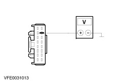
| | 3 Measure the voltage between the anti-theft alarm and double locking module, connector C2030b, pin 2, circuit 29-AA1 (OG/YE), wiring harness side and ground. |
| | Is battery voltage measured? Yes No LOCATE and REPAIR the break in the circuit between anti-theft alarm/double locking module and fuse 2.38 using the wiring diagrams. TEST the system for normal operation. |
| A8: TEST THE VOLTAGE AT THE ANTI-THEFT ALARM AND DOUBLE LOCKING MODULE |
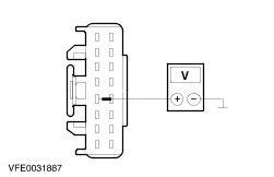
| | 1 Measure the voltage between the anti-theft alarm and double locking module, connector C2030b, pin 5, circuit 29-AA2 (OG/BU), wiring harness side and ground. |
| | Is battery voltage measured? Yes No LOCATE and REPAIR the break in the circuit between anti-theft alarm/double locking module and fuse 2.31 using the wiring diagrams. TEST the system for normal operation. |
| A9: TEST THE VOLTAGE AT THE ANTI-THEFT ALARM AND DOUBLE LOCKING MODULE |
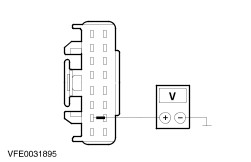
| | 1 Disconnect Anti-Theft Alarm and Double Locking Module C2030a. |
| | 2 Ignition switch in position II. |
| | 3 Measure the voltage between the anti-theft alarm and double locking module, connector C2030a, pin 7, circuit 15-AA80 (GN/WH), wiring harness side and ground. |
| | Is battery voltage measured? Yes No LOCATE and REPAIR the break in the circuit between anti-theft alarm/double locking module and fuse 2.1 using the wiring diagrams. TEST the system for normal operation. |
| A10: TEST THE GROUND CONNECTION OF THE ANTI-THEFT ALARM AND DOUBLE LOCKING MODULE |
| | 1 Ignition switch in position 0. |
| | 2 Measure the resistance between the anti-theft alarm and double locking module, connector C2030b, pin 6, circuit 91-AA57 (BN), wiring harness side and ground. |
| | Is a resistance of less than 2 Ohms registered? Yes No LOCATE and REPAIR the break in circuit 91-AA57 (BN) between anti-theft alarm/double locking module and ground point G203 using the wiring diagrams. TEST the system for normal operation. |
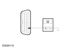
| A11: CHECK THE ISO 9141 BUS BETWEEN THE ANTI-THEFT ALARM/DOUBLE LOCKING MODULE AND THE DATA LINK CONNECTOR (DLC) FOR OPEN CIRCUIT |
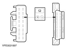
| | 1 Measure resistance between anti-theft alarm and double locking module, connector C2030b, pin 11, circuit 8-AA6 (WH), wiring harness side and DLC, connector C251, pin 7, circuit 8-RA10 (WH/BK), wiring harness side. |
| | Is a resistance of less than 2 Ohms registered? Yes No LOCATE and REPAIR the break in circuit 8-AA6 (WH) or 8-RA10 (WH/BK) between the anti-theft alarm/double locking module and the DLC using the wiring diagrams. TEST the system for normal operation. |
| A12: TEST THE ISO 9141 BUS FOR A SHORT TO VOLTAGE |
WARNING:After disconnecting the battery, wait at least 1 minute before any connectors of the safety retention system are disconnected, to avoid a deployment. Failure to follow this instruction may result in personal injury. |
WARNING:To avoid a deployment, do not use a radio keycode storage device when working on the safety retention system. Failure to follow this instruction may result in personal injury. |
NOTE:The number of modules connected to the ISO 9141 bus depends on the vehicle equipment level. Therefore not every vehicle will have all the modules mentioned below. |
| | 1 Disconnect Battery ground cable. |
| | 2 Disconnect ABS module C135. |
| | 3 Disconnect Fuel fired booster heater or heater (water) C1076. |
| | 4 Disconnect Safety retention system module C2041. |
| | 5 Disconnect Parking aid module C2023. |
| | 6 Disconnect Air suspension module C4014. |
| | 7 Connect Battery ground cable. |
| | 8 Ignition switch in position II. |
| | 9 Measure the voltage between the DLC, connector C251, pin 7, circuit 8-RA10 (WH/BK), wiring harness side and ground. |
| | Is a voltage registered? Yes LOCATE and RECTIFY the short to voltage in the circuits connected to soldered connection S235 with the aid of the Wiring Diagrams. TEST the system for normal operation. No |
| A13: TEST THE ISO 9141 BUS FOR A SHORT TO GROUND |
| | 1 Ignition switch in position 0. |
| | 2 Measure the resistance between the DLC, connector C251, pin 7, circuit 8-RA10 (WH/BK), wiring harness side and ground. |
| | Is a resistance of more than 10 kOhms registered? Yes TEST the anti-theft alarm/double locking module and RENEW it if necessary. TEST the system for normal operation. No LOCATE and RECTIFY the short to ground in the circuits connected to soldered connection S235 with the aid of the Wiring Diagrams. TEST the system for normal operation. |