| Diagnosis and Testing Refer to Wiring Diagrams Section 501-11, for schematic and connector information. Inspection and Verification - Verify the customer concern.
- Visually inspect for obvious signs of mechanical and electrical damage.
Visual Inspection Chart | Electrical | - Fuse(s)
- Grid Wire(s)
- Electrical connector(s)
- Switch(es)
- Circuit(s)
- Relay(s)
| - If an obvious cause for an observed or reported concern is found, correct the cause (if possible) before proceeding to the next step.
- If the cause is not visually evident, verify the symptom and refer to the Symptom Chart.
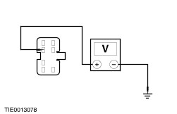
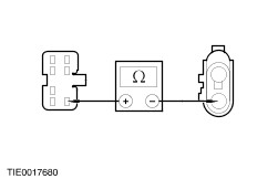
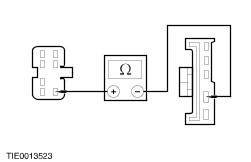
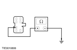
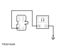
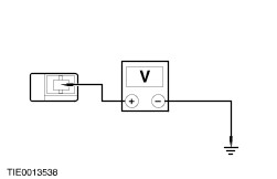
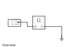
Symptom Chart | Symptom | Possible Sources | Action | | All power windows are inoperative | * Driver side power window control switch. | * CARRY OUT the Driver Side Power Window Control Switch Component Test. REFER to the Wiring Diagrams. | | * Circuit(s). | * | | A single power window is inoperative - driver side | * Driver side power window control switch. | * CARRY OUT the Driver Side Power Window Control Switch Component Test. REFER to the Wiring Diagrams. | | * Driver side front door window regulator motor. * One-touch down relay. * Circuit(s). | * | | A single power window is inoperative - passenger side | * Driver side power window control switch. | * CARRY OUT the Driver Side Power Window Control Switch Component Test. REFER to the Wiring Diagrams. | | * Passenger side power window control switch. | * CARRY OUT the Passenger Side Power Window Control Switch Component Test. REFER to the Wiring Diagrams. | | * Passenger side front door window regulator motor. * Circuit(s). | * | | The one-touch down feature is inoperative | * Driver side power window control switch. | * CARRY OUT the Driver Side Power Window Control Switch Component Test. REFER to the Wiring Diagrams. | | * One-touch down relay. * Circuit(s). | * | | The defrost system is inoperative | * Rear door/liftgate heated window glass control switch. * Rear door/liftgate heated window glass relay. * Heated windshield glass control switch. * Heated windshield glass relay. * Circuit(s). | * | | The defrost system will not shut off automatically | * Rear door/liftgate heated window glass control switch. * Rear door/liftgate heated window glass relay. * Heated windshield glass control switch. * Heated windshield glass relay. * Circuit(s). | * | Pinpoint Tests | PINPOINT TEST A : ALL POWER WINDOWS ARE INOPERATIVE | NOTE:Use a digital multimeter for all electrical measurements. | | TEST CONDITIONS | DETAILS/RESULTS/ACTIONS | | A1: CHECK FOR VOLTAGE TO THE DRIVER SIDE POWER WINDOW CONTROL SWITCH | | | 1 Disconnect Driver Side Power Window Control Switch C293 or Driver Side Power Window Control Switch C504b or Driver Side Power Window Control Switch C654b. | | | 2 Ignition switch in position II. | | | 3 Measure the voltage between the: | | | Is the voltage greater than 10 volts? Yes No REPAIR circuit 15-AJ7 (GN/BU). TEST the system for normal operation. | | A2: CHECK THE DRIVER SIDE POWER WINDOW CONTROL SWITCH GROUND CIRCUITS | | | 1 Ignition switch in position 0. | | | 2 Measure the resistance between the: | | | Are the resistances less than 5 ohms? Yes VERIFY the customer concern. No REPAIR circuit 31-AJ7 (BK/BU) or circuit 31-AJ40 (BK/GN). TEST the system for normal operation. | | PINPOINT TEST D : THE ONE-TOUCH DOWN FEATURE IS INOPERATIVE | NOTE:Use a digital multimeter for all electrical measurements. | | TEST CONDITIONS | DETAILS/RESULTS/ACTIONS | | D1: CHECK FOR VOLTAGE TO THE ONE-TOUCH DOWN RELAY | | | 1 Disconnect One-touch Down Relay C297 or One-touch Down Relay C528 or One-touch Down Relay C678. | | | 2 Ignition switch in position II. | | | 3 Measure the voltage between the: | | | Is the voltage greater than 10 volts? Yes No REPAIR circuit 15-AJ81 (GN/YE). TEST the system for normal operation. | | D2: CHECK CIRCUIT 33-AJ81 (YE) FOR CONTINUITY | | | 1 Ignition switch in position 0. | | | 2 Measure the resistance between the: | | | Is the resistance less than 5 ohms? Yes No REPAIR circuit 33-AJ81 (YE). TEST the system for normal operation. | | D3: CHECK THE ONE-TOUCH DOWN RELAY GROUND CIRCUIT | | | 1 Measure the resistance between the: | | | Is the resistance less than 5 ohms? Yes INSTALL a new one-touch down relay. TEST the system for normal operation. No REPAIR circuit 31-AJ81 (BK/YE) or circuit 31-AJ81 (BK). TEST the system for normal operation. | | PINPOINT TEST E : THE DEFROST SYSTEM IS INOPERATIVE | NOTE:Use a digital multimeter for all electrical measurements. | NOTE:This symptom covers the defrost system for the lifegate/rear door heated window glass, the heated exterior mirrors and the heated windshield. For the lifegate/rear door heated window glass and the heated exterior mirrors GO to E1. For the heated windshield GO to E17. | | TEST CONDITIONS | DETAILS/RESULTS/ACTIONS | | E1: CHECK THE REAR DOOR/LIFTGATE HEATED WINDOW GLASS CONTROL SWITCH LED | | | 1 Ignition switch in position II. | | | 2 Operate the rear door/liftgate heated window glass control switch | | | Does the rear door/liftgate heated window glass control switch LED illuminate? Yes For the rear door/liftgate heated window glass GO to E2. For the heated exterior mirrors GO to E5. No | | E2: CHECK FOR VOLTAGE TO THE REAR DOOR/LIFTGATE HEATED WINDOW GLASS | | | 1 Ignition switch in position 0. | | | 2 Disconnect Rear Door Heated Window Glass C262 or Rear Door Heated Window Glass C264 or Rear Door Heated Window Glass C473a or Rear Door Heated Window Glass C474a or Liftgate Heated Window Glass C1108. | | | 3 Ignition switch in position II. | | | 4 Operate the rear door/liftgate heated window glass control switch. | | | 5 Measure the voltage between the: Vehicles with liftgate - Liftgate heated window glass C1108, circuit 29S-HB34 (OG/BU), harness side and ground.
| | | Is the voltage greater than 10 volts? Yes No REPAIR circuit 29S-HB33 (OG/GN) or circuit 29S-HB34 (OG/BU). TEST the system for normal operation. | | E3: CHECK THE REAR DOOR/LIFTGATE HEATED WINDOW GLASS GROUND CIRCUIT | | | 1 Ignition switch in position 0. | | | 2 Disconnect Rear Door Heated Window Glass C263 or Rear Door Heated Window Glass C265 or Rear Door Heated Window Glass C473b or Rear Door Heated Window Glass 474b or Liftgate Heated Window Glass C1057. | | | 3 Measure the resistance between the: Vehicles with liftgate - Liftgate heated window glass C1057, circuit 31-HB34 (BK), harness side and ground.
| | | Is the resistance less than 5 ohms? Yes No REPAIR circuit 31-HB33 (BK) or circuit 31-HB34 (BK). TEST the system for normal operation. | | E4: CHECK THE CONTINUITY OF THE REAR DOOR/LIFTGATE HEATED WINDOW GLASS | | | 1 Measure the resistance between the: Vehicles with liftgate - Liftgate heated window glass C1108, component side and the liftgate heated window glass C1057, component side.
| | | Is the resistance less than 5 ohms? Yes VERIFY the customer concern. No INSTALL a new rear door/liftgate heated window glass. REFER to: (501-11 Glass, Frames and Mechanisms) Rear Door Window Glass (Removal and Installation), Liftgate Window Glass (Removal and Installation). TEST the system for normal operation. | | E5: CHECK FOR VOLTAGE TO THE INOPERATIVE HEATED EXTERIOR MIRROR | | | 1 Ignition switch in position 0. | | | 2 Disconnect Heated Exterior Mirror C290 or Heated Exterior Mirror C291 or Heated Exterior Mirror C2011 or Heated Exterior Mirror C2012. | | | 3 Ignition switch in position II. | | | 4 Operate the rear door/liftgate heated window glass control switch. | | | 5 Measure the voltage between the: | | | Is the voltage greater than 10 volts? Yes No REPAIR circuit 29S-HB15 (OG/BK) or circuit 29S-HB28 (OG/GN). TEST the system for normal operation. | | E6: CHECK THE INOPERATIVE HEATED EXTERIOR MIRROR GROUND CIRCUIT | | | 1 Ignition switch in position 0. | | | 2 Measure the resistance between the: | | | Is the resistance less than 5 ohms? Yes INSTALL a new heated exterior mirror.
REFER to: Exterior Mirror (501-09 Rear View Mirrors, Removal and Installation).
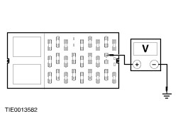
TEST the system for normal operation. No REPAIR circuit 31-HB15 (BK) or circuit 31-HB28 (BK). TEST the system for normal operation. | | E7: CHECK THE VOLTAGE TO THE CENTRAL JUNCTION BOX (CJB) FUSE 17 (15A) | | | 1 Ignition switch in position 0. | | | 2 Disconnect Fuse 17 (15A). | | | 3 Ignition switch in position II. | | | 4 Operate the rear door/liftgate heated window glass control switch. | | | 5 Measure the voltage between the: | | | Is the voltage greater than 10 volts? Yes No | | E8: CHECK CIRCUIT 29S-HB31 (OG) FOR CONTINUITY | NOTE:The circuit numbers change at the spliced joint S250 or S272 | | | 1 Ignition switch in position 0. | | | 2 Disconnect Rear Door/Liftgate Heated Window Glass Control Switch C239 or Rear Door/Liftgate Heated Window Glass Control Switch C241. | | | 3 Measure the resistance between the: | | | Is the resistance less than 5 ohms? Yes No REPAIR circuit 29S-HB2 (OG/BU) or circuit 29S-HB31 (OG). TEST the system for normal operation. | | E9: CHECK THE REAR DOOR/LIFTGATE HEATED WINDOW GLASS CONTROL SWITCH GROUND CIRCUIT | | | 1 Measure the resistance between the: | | | Is the resistance less than 5 ohms? Yes VERIFY the customer concern. No REPAIR circuit 31-LH37 (BK). TEST the system for normal operation. | | E10: CHECK FOR VOLTAGE TO THE REAR DOOR/LIFTGATE HEATED WINDOW GLASS RELAY | | | 1 Ignition switch in position 0. | | | 2 Disconnect Rear Door/Liftgate Heated Window Glass Relay C1005 or Rear Door/Liftgate Heated Window Glass Relay C2021. | | | 3 Ignition switch in position II. | | | 4 Measure the voltage between the: | | | Is the voltage greater than 10 volts? Yes No REPAIR circuit 15-HB20 (GN/BK). TEST the system for normal operation. | | E11: CHECK THE REAR DOOR/LIFTGATE HEATED WINDOW GLASS RELAY GROUND CIRCUIT | | | 1 Ignition switch in position 0. | | | 2 Measure the resistance between the: | | | Is the resistance less than 5 ohms? Yes No REPAIR circuit 31-HB23 (BK). TEST the system for normal operation. | | E12: CHECK THE REAR DOOR/LIFTGATE HEATED WINDOW GLASS RELAY SWITCHED GROUND CIRCUIT | | | 1 Operate the rear door/liftgate heated window glass control switch. | | | 2 Measure the resistance between the: | | | Is the resistance less than 5 ohms? Yes No | | E13: CHECK FOR VOLTAGE TO THE REAR DOOR/LIFTGATE HEATED WINDOW GLASS RELAY | | | 1 Ignition switch in position II. | | | 2 Measure the voltage between the: | | | Is the voltage greater than 10 volts? Yes No REPAIR circuit 15-HB21 (GN/OG). TEST the system for normal operation. | | E14: CHECK FOR CONTINUITY BETWEEN THE REAR DOOR/LIFTGATE HEATED WINDOW GLASS RELAY AND THE CJB FUSE 17 (15A) | | | 1 Measure the resistance between the: | | | Is the resistance less than 5 ohms? Yes INSTALL a new rear door/liftgate heated window glass relay. TEST the system for normal operation. No REPAIR circuit 29S-HB1 (OG/YE) or circuit 29S-HB21 (OG/GN). TEST the system for normal operation. | | E15: CHECK THE REAR DOOR/LIFTGATE HEATED WINDOW GLASS CONTROL SWITCH GROUND CIRCUIT | | | 1 Disconnect Rear Door/Liftgate Heated Window Glass Control Switch C239 or Rear Door/Liftgate Heated Window Glass Control Switch C241. | | | 2 Measure the resistance between the: | | | Is the resistance less than 5 ohms? Yes No REPAIR circuit 31-HB22 (BK). TEST the system for normal operation. | | E16: CHECK FOR CONTINUITY BETWEEN THE REAR DOOR/LIFTGATE HEATED WINDOW GLASS RELAY AND THE REAR DOOR/LIFTGATE HEATED WINDOW GLASS CONTROL SWITCH | | | 1 Measure the resistance between the: | | | Is the resistance less than 5 ohms? Yes VERIFY the customer concern. No REPAIR circuit 31S-HB20 (BK/GN). TEST the system for normal operation. | | E17: CHECK THE HEATED WINDSHIELD GLASS CONTROL SWITCH LED | | | 1 Ignition switch in position III. | | | 2 Ignition switch in position II. | | | 3 Operate the heated windshield glass control switch. | | | Does the heated windshield glass control switch LED illuminate? Yes No | | E18: CHECK THE OPERATION OF THE HEATED WINDSHIELD GLASS RIGHT-HAND RELAY | | | 1 Operate the heated windshield glass control switch. | | | Does the heated windshield glass right-hand relay click? Yes No | | E19: CHECK FOR VOLTAGE TO THE HEATED WINDSHIELD GLASS GRID WIRES | | | 1 Ignition switch in position 0. | | | 2 Disconnect Heated Windshield Glass Grid Wire C21 and Heated Windshield Glass Grid Wire C23 or Heated Windshield Glass Grid Wire C2045b and Heated Windshield Glass Grid Wire C2046b. | | | 3 Ignition switch in position III. | | | 4 Ignition switch in position II. | | | 5 Operate the heated windshield glass control switch. | | | 6 Measure the voltage between the: | | | Is the voltage greater than 10 volts? Yes No | | E20: CHECK THE HEATED WINDSHIELD GLASS GRID WIRE GROUND CIRCUITS | | | 1 Ignition switch in position 0. | | | 2 Disconnect Heated Windshield Glass Grid Wire C22 and Heated Windshield Glass Grid Wire C24 or Heated Windshield Glass Grid Wire C2045a and Heated Windshield Glass Grid Wire C2046a. | | | 3 Measure the resistance between the: | | | Is the resistance less than 5 ohms? Yes No REPAIR circuit 31-HB12 (BK) or circuit 31-HB25 (BK). TEST the system for normal operation. | | E21: CHECK THE HEATED WINDSHIELD GLASS FOR CONTINUITY | | | 1 Measure the resistance between the: | | | Is the resistance less than 5 ohms? Yes VERIFY customer concern. No | | E22: CHECK THE OPERATION OF THE HEATED WINDSHIELD GLASS LEFT-HAND RELAY | | | 1 Operate the heated windshield glass control switch. | | | Does the heated windshield glass left-hand relay click? Yes No | | E23: CHECK FOR VOLTAGE TO THE CJB FUSE 2.2 (5A) | | | 1 Ignition switch in position 0. | | | 2 Disconnect Fuse 2.2 (5A). | | | 3 Ignition switch in position II. | | | 4 Operate the heated windshield glass control switch. | | | 5 Measure the voltage between the CJB fuse 2.2 (5A), circuit 30S-HB10 (RD/GN), input side and ground. | | | Is the voltage greater than 10 volts? Yes No | | E24: CHECK THE HEATED WINDSHIELD GLASS CONTROL SWITCH LED GROUND CIRCUIT | | | 1 Ignition switch in position 0. | | | 2 Disconnect Heated Windshield Glass Control Switch C25 or Heated Windshield Glass Control Switch C2025. | | | 3 Measure the resistance between the: | | | Is the resistance less than 5 ohms? Yes No REPAIR circuit 33-LH24 (YE/BU). TEST the system for normal operation. | | E25: CHECK FOR CONTINUITY BETWEEN THE HEATED WINDSHIELD GLASS CONTROL SWITCH AND THE CJB FUSE 2.2 (5A) | | | 1 Measure the resistance between the: | | | Is the resistance less than 5 ohms? Yes INSTALL a new heated windshield glass control switch. TEST the system for normal operation. No REPAIR circuit 30S-HB6 (RD/YE). TEST the system for normal operation. | | E26: CHECK FOR SWITCH VOLTAGE TO THE HEATED WINDSHIELD GLASS RIGHT-HAND RELAY - VEHICLES BUILT UP TO 08/2003 | | | 1 Ignition switch in position 0. | | | 2 Disconnect Heated Windshield Glass Right-hand Relay C2019. | | | 3 Ignition switch in position III. | | | 4 Ignition switch in position II. | | | 5 Measure the voltage between the heated windshield glass right-hand relay C2019 pin 86, circuit 30S-HB7 (RD/BU), harness side and ground. | | | Is the voltage greater than 10 volts? Yes No REPAIR circuit 30S-HB7 (RD/BU). TEST the system for normal operation. | | E27: CHECK THE HEATED WINDSHIELD GLASS RIGHT-HAND RELAY GROUND CIRCUIT - VEHICLES BUILT UP TO 08/2003 | | | 1 Measure the resistance between the heated windshield glass right-hand relay C2019 pin 85, circuit 31-HB7 (BK), harness side and ground. | | | Is the resistance less than 5 ohms? Yes INSTALL a new heated windshield glass right-hand relay. TEST the system for normal operation. No REPAIR circuit 31-HB7 (BK). TEST the system for normal operation. | | E28: CHECK FOR SWITCH VOLTAGE TO THE HEATED WINDSHIELD GLASS RIGHT-HAND RELAY - VEHICLES BUILT FROM 08/2003 | | | 1 Ignition switch in position 0. | | | 2 Disconnect Heated Windshield Glass Right-hand Relay C1002. | | | 3 Ignition switch in position III. | | | 4 Ignition switch in position II. | | | 5 Measure the voltage between the heated windshield glass right-hand relay C1002 pin 1, circuit 30S-HB7 (RD/BU), harness side and ground. | | | Is the voltage greater than 10 volts? Yes No REPAIR circuit 30S-HB7 (RD/BU). TEST the system for normal operation. | | E29: CHECK THE HEATED WINDSHIELD GLASS RIGHT-HAND RELAY GROUND CIRCUIT - VEHICLES BUILT FROM 08/2003 | | | 1 Measure the resistance between the heated windshield glass right-hand relay C1002 pin 2, circuit 31-HB7 (BK), harness side and ground. | | | Is the resistance less than 5 ohms? Yes INSTALL a new heated windshield glass right-hand relay. TEST the system for normal operation. No REPAIR circuit 31-HB7 (BK). TEST the system for normal operation. | | E30: CHECK FOR BATTERY VOLTAGE TO THE HEATED WINDSHIELD GLASS RIGHT-HAND RELAY - VEHICLES BUILT UP TO 08/2003 | | | 1 Ignition switch in position 0. | | | 2 Disconnect Heated Windshield Glass Right-hand Relay C2019. | | | 3 Measure the voltage between the heated windshield glass right-hand relay C2019 pin 30, circuit 15-HB8 (GN/RD), harness side and ground. | | | Is the voltage greater than 10 volts? Yes No REPAIR circuit 15-HB8 (GN/RD). TEST the system for normal operation. | | E31: CHECK FOR CONTINUITY BETWEEN THE HEATED WINDSHIELD GLASS RIGHT-HAND RELAY AND THE HEATED WINDSHIELD GLASS RIGHT-HAND GRID WIRE - VEHICLES BUILT UP TO 08/2003 | | | 1 Measure the resistance between the heated windshield glass right-hand relay C2019 pin 87, circuit 30S-HB25 (RD/BU), harness side and the heated windshield glass right-hand grid wire C2046b pin 1, circuit 30S-HB25 (RD/BU), harness side. | | | Is the resistance less than 5 ohms? Yes INSTALL a new heated windshield glass right-hand relay. TEST the system for normal operation. No REPAIR circuit 30S-HB25 (RD/BU). TEST the system for normal operation. | | E32: CHECK FOR BATTERY VOLTAGE TO THE HEATED WINDSHIELD GLASS RIGHT-HAND RELAY - VEHICLES BUILT FROM 08/2003 | | | 1 Ignition switch in position 0. | | | 2 Disconnect Heated Windshield Glass Right-Hand Relay C1002. | | | 3 Measure the voltage between the heated windshield glass right-hand relay C1002 pin 3, circuit 15-HB8 (GN/RD), harness side and ground. | | | Is the voltage greater than 10 volts? Yes No REPAIR circuit 15-HB8 (GN/RD). TEST the system for normal operation. | | E33: CHECK FOR CONTINUITY BETWEEN THE HEATED WINDSHIELD GLASS RIGHT-HAND RELAY AND THE HEATED WINDSHIELD GLASS RIGHT-HAND GRID WIRE - VEHICLES BUILT FROM 08/2003 | | | 1 Measure the resistance between the heated windshield glass right-hand relay C1002 pin 5, circuit 30S-HB25 (RD/BU), harness side and the heated windshield glass right-hand grid wire C21 pin 1, circuit 30S-HB25 (RD/BU), harness side. | | | Is the resistance less than 5 ohms? Yes INSTALL a new heated windshield glass right-hand relay. TEST the system for normal operation. No REPAIR circuit 30S-HB25 (RD/BU). TEST the system for normal operation. | | E34: CHECK THE HEATED WINDSHIELD GLASS CURRENT | | | 1 Connect Heated Windshield Grid Wire C22 and Heated Windshield Grid Wire C24 or Heated Windshield Grid Wire C2045a and Heated Windshield Grid Wire C2046a. | | | 2 Operate the heated windshield glass control switch. | | | 3 Measure the current between the: | | | Is the current less than 27A? Yes INSTALL a new heated windshield glass.
REFER to: Windshield Glass (501-11 Glass, Frames and Mechanisms, Removal and Installation).
TEST the system for normal operation. No VERIFY the customer concern. | | E35: CHECK FOR VOLTAGE TO THE HEATED WINDSHIELD GLASS LEFT-HAND RELAY | | | 1 Ignition switch in position 0. | | | 2 Disconnect Heated Windshield Glass Left-Hand Relay C1001 or Heated Windshield Glass Left-Hand Relay C2018. | | | 3 Ignition switch in position III. | | | 4 Ignition switch in position II. | | | 5 Measure the voltage between the: | | | Is the voltage greater than 10 volts? Yes No REPAIR circuit 29-HB11 (OG/GN). TEST the system for normal operation. | | E36: CHECK FOR CONTINUITY BETWEEN THE HEATED WINDSHIELD GLASS LEFT-HAND RELAY AND SWITCHED GROUND | | | 1 Ignition switch in position 0. | | | 2 Operate the heated windshield glass control switch. | | | 3 Measure the resistance between the: | | | Is the resistance less than 5 ohms? Yes INSTALL a new heated windshield glass left-hand relay. TEST the system for normal operation. No | | E37: CHECK FOR VOLTAGE TO THE HEATED WINDSHIELD GLASS LEFT-HAND RELAY | | | 1 Ignition switch in position 0. | | | 2 Disconnect Heated Windshield Glass Left-Hand Relay C1001 or Heated Windshield Glass Left-Hand Relay C2018. | | | 3 Measure the voltage between the: | | | Is the voltage greater than 10 volts? Yes No REPAIR circuit 15-HB10 (GN/BK). TEST system for normal operation. | | E38: CHECK FOR CONTINUITY BETWEEN THE HEATED WINDSHIELD GLASS CONTROL SWITCH AND THE CJB FUSE 2.2 (5A) | | | 1 Disconnect Heated Windshield Glass Control Switch C25 or Heated Windshield Glass Control Switch C2025. | | | 2 Measure the resistance between the: | | | Yes INSTALL a new windshield heated left-hand relay. TEST the system for normal operation. No REPAIR circuit 15S-LH24 (GN/RD) or circuit 30S-HB6 (RD/YE). TEST the system for normal operation. | | E39: CHECK HEATED WINDSHIELD GLASS CONTROL SWITCH GROUND CIRCUIT | | | 1 Disconnect Heated Windshield Glass Control Switch C25 or Heated Windshield Glass Control Switch C2025. | | | 2 Measure the resistance between the: | | | Is the resistance less than 5 ohms? Yes No Repair circuit 32-HB9 (WH/VT). TEST the system for normal operation. | | E40: CHECK FOR CONTINUITY BETWEEN THE HEATED WINDSHIELD GLASS LEFT-HAND RELAY AND THE HEATED WINDSHIELD GLASS CONTROL SWITCH | | | 1 Measure the resistance between the: | | | Is the resistance less than 5 ohms? Yes INSTALL a new heated windshield glass control switch. TEST the system for normal operation. No REPAIR circuit 31S-HB9 (BK/WH). TEST the system for normal operation. | | PINPOINT TEST F : THE DEFROST SYSTEM WILL NOT SHUT OFF AUTOMATICALLY | NOTE:Use a digital multimeter for all electrical measurements. | NOTE:This symptom covers the defrost system for the rear door/liftgate heated window glass, the heated exterior mirrors and the heated windshield. For the rear door/liftgate heated window glass and the heated exterior mirrors Go to F1. For the heated windshield Go to F2. | | TEST CONDITIONS | DETAILS/RESULTS/ACTIONS | | F1: CHECK CIRCUIT 31S-HB20 (BK/GN) FOR SHORT TO GROUND | | | 1 Disconnect Rear Door/Liftgate Heated Window Glass Relay C1005 or Rear Door/Liftgate Heated Window Glass Relay C2021. | | | 2 Measure the resistance between the | | | Is the resistance greater than 10,000 ohms? Yes VERIFY the customer concern. No REPAIR circuit 31S-HB20 (BK/GN). TEST the system for normal operation. | | F2: CHECK CIRCUIT 31S-HB9 (BK/WH) FOR SHORT TO GROUND | | | 1 Disconnect Heated Windshield Glass Left-hand Relay C1001 or Heated Windshield Glass Left-hand Relay C2018. | | | 2 Measure the resistance between the: | | | Is the resistance greater than 10,000 ohms? Yes VERIFY the customer concern. No REPAIR circuit 31S-HB9 (BK/WH). TEST the system for normal operation. | |