
Sprinter 3500 L5-2.7L DSL Turbo (2004)
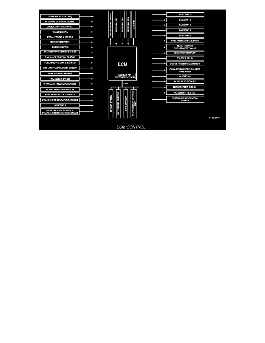
ECM Control
If a sensor should fail, provided the fault is not serious, the ECM will continue to operate the engine in Limp-Home Mode (emergency mode) using a
default value for the missing signal. The ECM ensures that, continuing to operate the engine will not cause damage or effect safety, otherwise a Engine
shut-off process will be carried out.
ECM Control Strategy The engine control module is involved with a variety of functions such as:
-
Individual injector activation
-
Engine idle speed control to ensure smooth engine idling independent of engine load
-
Ride comfort function such as anti jerk control: The CDI control module detects irregularities in engine speed (resulting, for example, from load
changes or gear shift) from the signal supplied by the crankshaft position sensor and reduces them by adjusting the quantity injected into each of
the cylinders
-
Constant RPM (high idle feature) for ambulance vehicle bodies equipped with electrical appliances
-
Starter control, immobilizer, cruise control, kick down, air conditioner
-
Maintenance computer ASSYST (optional)
-
Glow plug for pre-heating, post heating and intermittent heating
-
Error code memory/diagnostics, communication interface for diagnosis and handling the fault codes
-
The maximum vehicle speed is programmable from 19-82 m.p.h. The standard is 82 m.p.h.
New software has been loaded to the ECM for EGR control. This is due to the wider operating range and larger volume of recirculated gas. There is a
considerable number of new, adapted, and optimized functions, particularly with regard to injection, EGR, boost control, sensing of the input parameters
and the signaling of the actuators.
-
The rail pressure control achieved by signaling the quantity control valve in the high pressure pump and the pressure regulator results in reduced
power consumption of high pressure pump and in lowering fuel pressures
-
Individual cylinder torque control for smooth engine running: using the crankshaft position sensor signals, the ECM detect non-uniform engine
running results from uneven torque contributions of the individual cylinders and adjust the injection quantities of the individual injectors so that all
cylinders make the same torque contribution
-
A relay is used for activating the electric in-tank fuel pump
-
Heated crankcase ventilation to ensure pressure compensation even at low temperatures
-
Improved boost pressure control using an electric variable nozzle turbine actuator with position feed back
-
Controlled fuel heating using the high pressure pump closed-loop control
-
Translation of the drive input received from the accelerator pedal module which is equipped with dual hall sensors
-
Measurement of the intake air mass using new mass air flow (MAF) sensor with increase precision and extended measuring range
-
O2 sensor for measuring the amount of oxygen in the exhaust in order to calculate the air to fuel ratio. With the intake air mass being known, the
injected fuel quantity can be calculated from the air to fuel ratio
-
Activation of the 02 sensor heater to burn off deposits
-
Full load EGR with a more precise, model based EGR closed-loop control. The ECM calculates the EGR rate from the various sensor signals.
Using the calculate EGR rate in percent instead of the fresh air mass flow as a control parameter enables a more precise control of the EGR rate as
well as better correction of the target value.
The oxygen sensor signal can be used in combination with the mass air flow signal, the injection quantity signal and pressure and temperature