
Sprinter 3500 L5-2.7L DSL Turbo (2004)
near the bottom of the page.
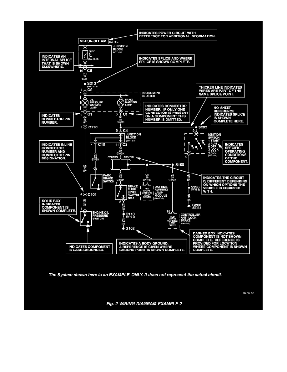
General Information (Part 2 of 2)
All switches, components, and modules are shown in the at rest position with the doors closed and the key removed from the ignition.
Components are shown two ways. A solid line around a component indicates that the component is complete. A dashed line around the component
indicates that the component is being shown is not complete. Incomplete components have a reference number to indicate the page where the
component is shown complete. To find any diagram sheets referred to by number only, go to Vehicle / Diagrams / Electrical / Diagrams By Number.
See: Diagrams/Electrical Diagrams/Diagrams By Number