
Sprinter 3500 L5-2.7L DSL Turbo (2004)
Theses references will be in the form of unique diagram identification numbers (i.e. 8W-16-4, 8W-25-2, etc). All diagram sheets are identified with this
unique ID number in their captions.
Diagrams sheets being referred to that may reside outside of the set of diagrams you are viewing can be accessed by clicking on the hyperlink for
"Diagrams By Number" which is provided with all sets of diagrams.
PLEASE NOTE: When locating diagrams by their ID numbers, some diagrams may appear to be missing because of gaps in the number sequences.
These "gaps" are actually for diagrams that do not apply to the vehicle model selected.
Connector Replacement
REMOVAL
1. Disconnect battery
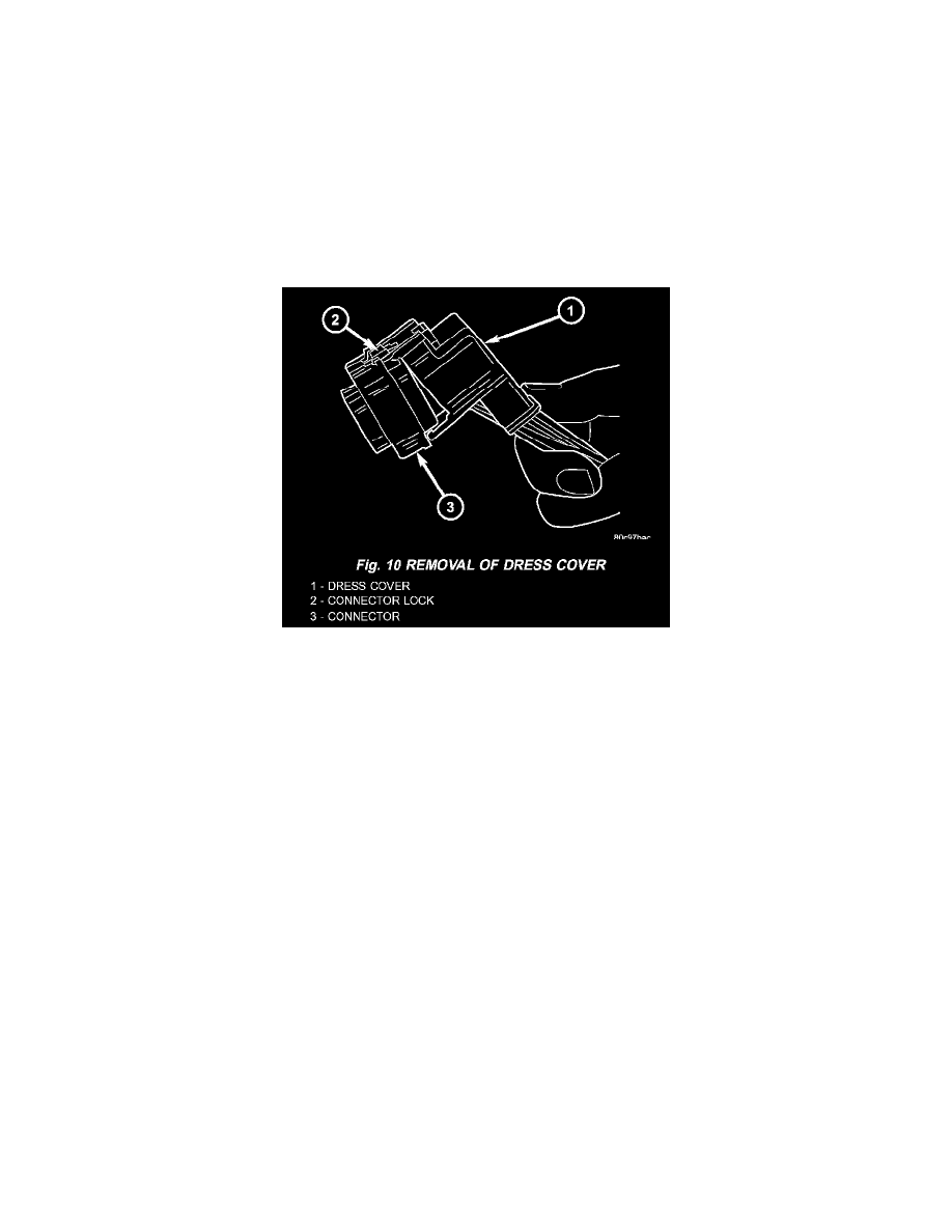
Fig.10 Removal Of Dress Cover
2. Release Connector Lock (Fig. 10).
3. Disconnect the connector being repaired from its mating half/component.
4. Remove the dress cover (if applicable) (Fig. 10).