
Tracker 4x2 L4-1.6L VIN 6 (1995)
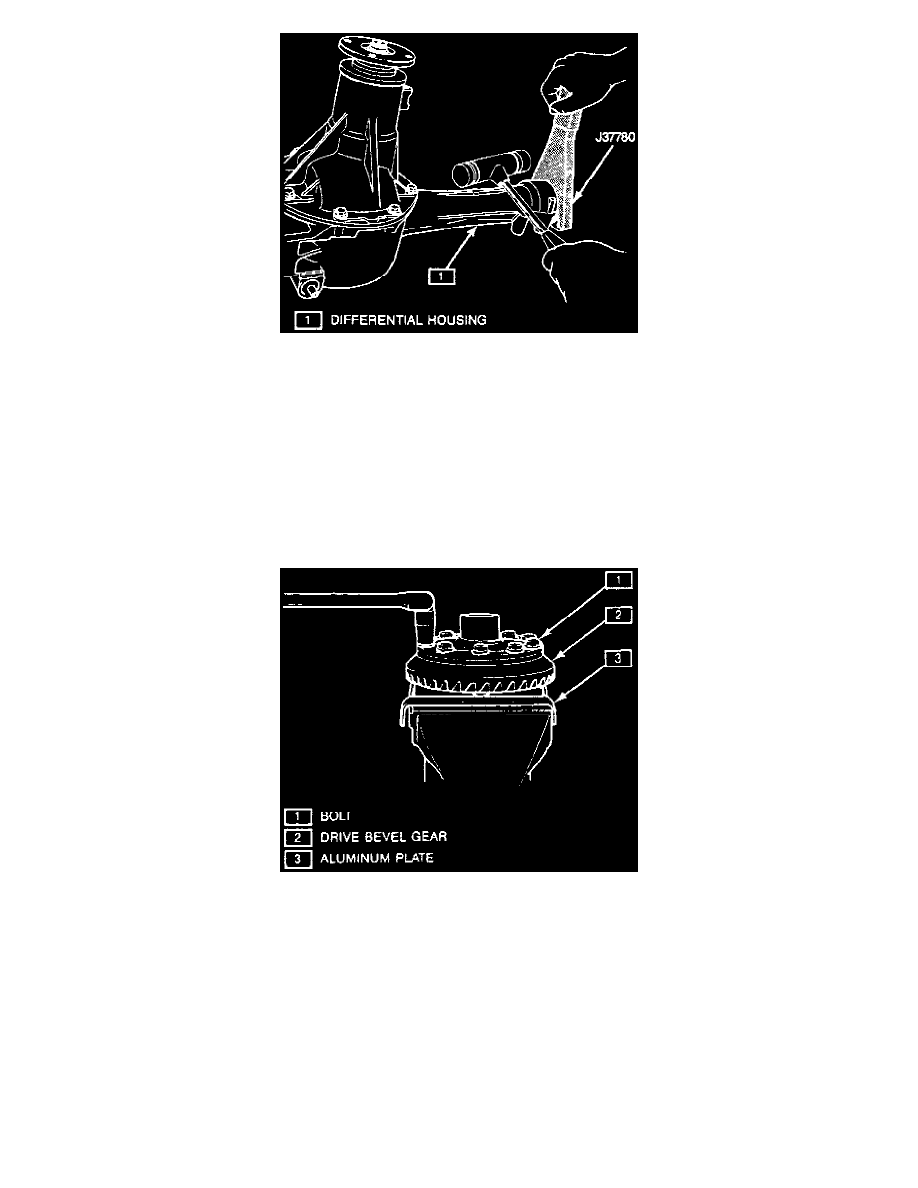
Fig. 4 Drive Shaft Removal.
Disassemble
1. Remove front RH driveshaft using plastic hammer and axle removal tool No. J-37780, or equivalent, Fig. 4.
2. Remove differential assembly from housing.
3. Mount differential assembly, using differential holding tool Nos. J-37769 and J-3289-01, or equivalent.
4. Mark differential side bearing caps for installation.
5. Remove side bearing lock plate, caps, adjusters, outer races and bevel pinion and gear assembly.
6. Rotate differential assembly using flange holding tool No. J-8614-01, or equivalent.
7. Remove universal joint flange nut, bevel pinion, flange and oil seal using seal removal tool Nos. J-8614-01 and J-26941, or equivalent.
8. Remove differential side bearing using bearing removal tool Nos. J-22888 and J-8107-4, or equivalent.
Fig. 5 Bevel Gear Removal.
9. Remove bevel gear attaching bolts, then the gear, Fig. 5. When mounting differential in a vise, use aluminum plates to avoid damage.
10. Drive out spring pin. Disassemble differential side gears, pinions, washers and shaft in differential case.
11. Press out bevel pinion gear using side bearing remover tool No. J-22912-01, or equivalent.
12. Drive out bevel pinion bearing outer race using suitable tools. Bevel gear and pinion must be replaced as a set.
ASSEMBLE
1. Assemble bevel pinion bearing outer races using bearing installer tool Nos. J-8092, J-37759 and J-37758, or equivalents.
2. Assemble differential side gear and side pinion with pinion shaft.