
Tracker 4x2 L4-1590cc 1.6L (1991)
Valve: Service and Repair
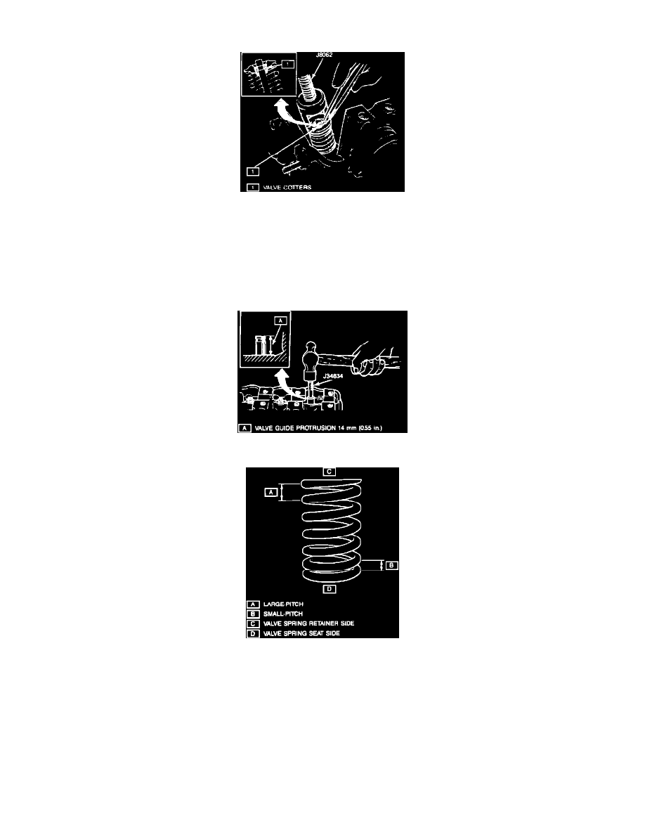
Fig. 14 Valve Cotter Removal
1.
Remove cylinder head assembly. Refer to CYLINDER HEAD for removal procedure.
2.
Using valve spring compressor tool No. J8062, compress valve springs and remove valve cotters, Fig. 14.
3.
Release valve lifter tool and remove valve spring retainers and valve springs.
4.
Remove valves from cylinder head. Before removing valves from head, ensure there are no burrs on valve stem from spring removal
procedure.
5.
Using valve guide oil seal removal tool No. J37281-A or J37755, remove valve stem oil seals and valve spring seats.
Fig. 15 Valve Guide Installation
Fig. 16 Valve Spring Installation
6.
Reverse procedure to install noting the following:
a.
Install new valve guides by driving out valve guides using valve guide removal tool No. J34833 toward the valve spring side.
b.
Ream valve guide holes using valve guide reamer tool No. J34832 to remove any burrs and to ensure that the hole is perfectly round.
c.
Install valve guides by heating cylinder head uniformly at a temperature of 176-212°F to prevent head distortion. Using valve guide
installation tool No. J34834, drive valve guide into cylinder head leaving a .55 inch protrusion above the cylinder head, Fig. 15.
d.
Ream valve guide bore after installation into the cylinder head using valve guide reamer too No. J34831.
e.
Install new valve stem oil seals and install them with oil seal installation tool No. J34835.
f.
Install valve springs with small pitch end is on the valve seat side, Fig. 16.