
Tracker 4x2 L4-1590cc 1.6L (1991)
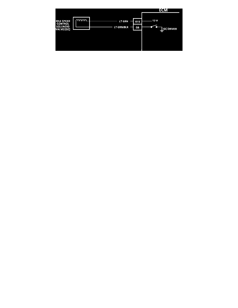
Wiring Diagram For Chart C-2
CIRCUIT DESCRIPTION:
The ECM controls a solenoid to regulate an opening at the throttle body. The amount of the opening determines the idle speed. The ISC is regulated
according to engine load. A stalling condition or rough idle could be caused by the ISC valve not functioning properly.
TEST DESCRIPTION: The numbers below refer to circled numbers on the diagnostic chart.
1.
This will quickly tell if the ECM will increase the idle for added engine load.
2.
If the solenoid has high resistance or no resistance, the valve will not operate properly.
3.
This will simulate the ECM command for the ISC valve to open.
4.
This test the circuit supplying B+ to the ISC valve.
5.
This will check the ISC valve Driver circuit in the ECM.
6.
Follow the ECM check in the Electrical and Electronic Specifications.