
Tracker 4x2 L4-1590cc 1.6L (1991)
Ignition Control Module: Testing and Inspection
Igniter Assembly
1.
Disconnect the igniter electrical connector.
2.
Remove the two screws and igniter from the ignition coil mounting bracket.
3.
Assemble two new 1.5 volt batteries in series to make a 3.0 volt power source.
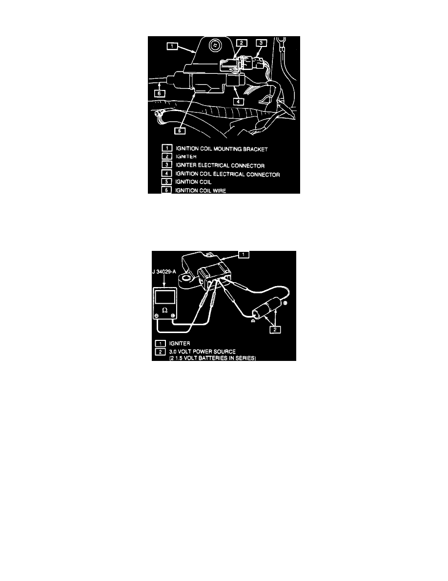
Inspecting Igniter
4.
Connect the positive (+) lead of a digital volt meter to terminal G of the igniter. Connect the negative (-) lead of the volt meter to the OC terminal
of the igniter.
5.
Connect the positive (+) lead of the 3.0 volt power source to the IB terminal of the igniter. Connect the negative (-) of the power source to the G
terminal of the igniter.
6.
Check for continuity between terminals G and OC with 3.0 volts applied to the IB terminal. If the igniter is not conductive, replace the igniter.
7.
Disconnect the power leads from the igniter. Check for continuity between the G and OC terminals of the igniter without 3.0 volts applied. If the
igniter is conductive, replace the igniter.