
Tracker 4x2 L4-1590cc 1.6L (1991)
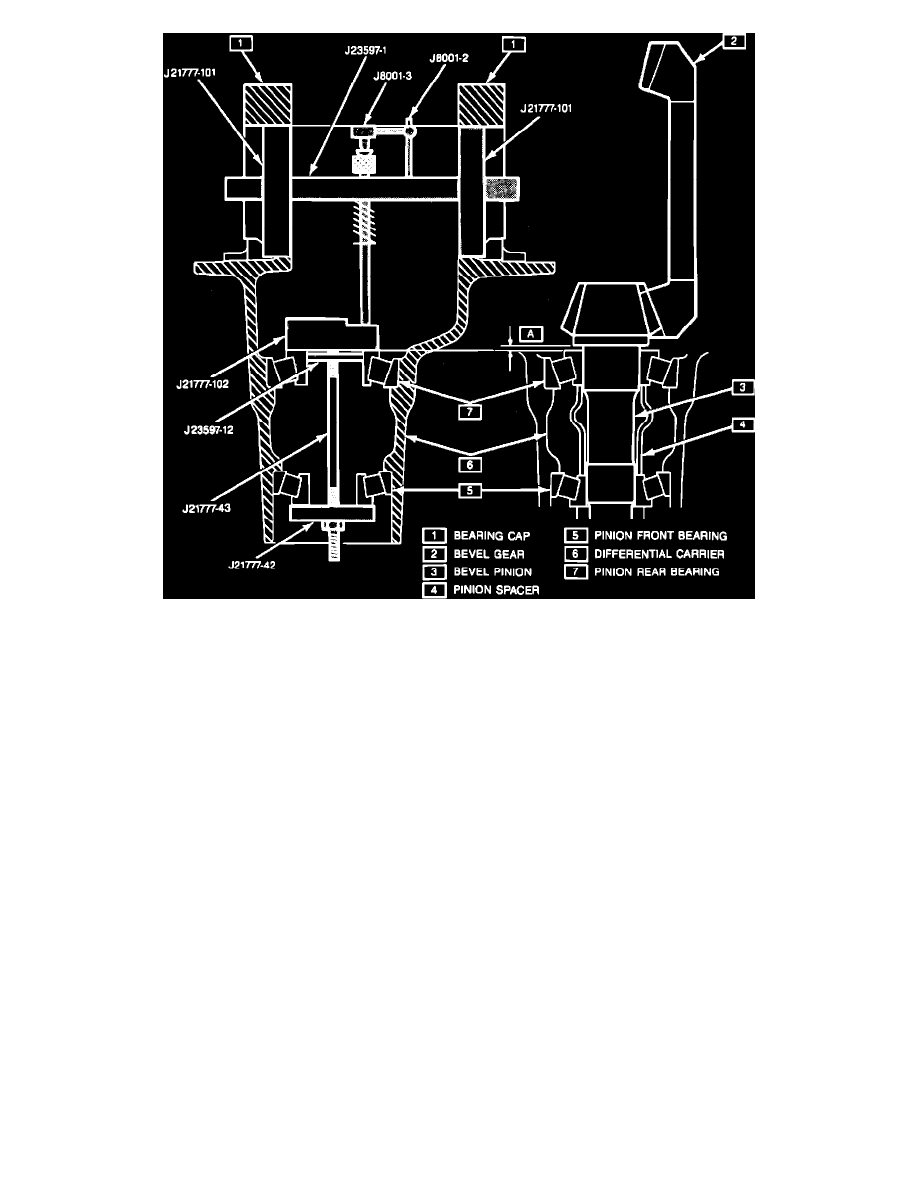
Fig. 7 Bevel Pinion Mounting Distance
Assembly
1.
Assemble bevel pinion bearing outer races using bearing installer tool Nos. J8092, J37759 and J37758, or equivalent.
2.
Assemble differential side gear and side pinion with pinion shaft.
3.
Mount dial indicator to top surface of side gear. Move lower end of side gear up and down, noting movement of indicator, Fig. 5.
4.
Install a .043 inch thrust washer and ensure a .005-.014 inch side gear thrust play is obtained.
5.
Drive spring pin in until it is flush with the differential case surface.
6.
Install bevel gear to differential case and torque bolts to 70 ft. lbs. Use GM Loctite thread locking kit (part No. 1052624) for bevel gear bolts.
7.
Mount dial indicator tool to back of side gear, Fig. 6.
8.
Install a .043 inch thrust washer and side thrust gear installation tool No. J35138, or equivalent onto differential side gear.
9.
Move tool up and down in a straight forward manner and ensure a side gear thrust play of .005-.014 inch is obtained.
10.
Install side bearings using bearing installation tool Nos. J8092 and J24433, or equivalent. Be sure to use side bearing removal tool No. J8107-4,
or equivalent to protect the lower bearing.
11.
Install depth gauge setting tool No. J21777, or equivalent while holding bearing in position, Fig. 7. Use low step on the gauge plate.
12.
Torque tool nut to 19 inch lbs. and rotate gauge plate several times to seat bearings.
13.
Torque tool nut to 19 inch lbs. or until gauge plate rotates smoothly with torque wrench.
14.
Install pinion setting gauge tool No. J23597, or equivalent and assemble the gauge shaft in the carrier so that the dial indicator rod is centered on
the gauging area of the gauge block.
15.
Install side bearing caps and torque bolts to 63 ft. lbs.
16.
Adjust dial indicator until a zero reading is obtained.
17.
Adjust the position of gauge shaft mounting post so contact button touches the indicator pad.
18.
Push the dial indicator downward into the gauge plate until the needle rotates 3/4 of a turn then tighten in this position.
19.
Slowly rotate the gauge shaft back and forth. At the point of greatest deflection, reset the dial indicator to zero. Repeat and ensure zero reading.
20.
Rotate the gauge shaft until the dial indicator rod no longer touches the gauge plate.
21.
Read movement on the dial indicator. Total movement on the dial indicator indicates thickness of shim required.
22.
Assemble pinion rear bearing, pinion shim and bevel pinion assembly.
23.
Install front bearing to differential carrier with new spacer inserted.
24.
Install oil seal into differential carrier until seal is flush with carrier end. Apply grease to lip of seal.
25.
Install pinion washer and nut. Hold pinion flange and rotate pinion to seat bearing. Tighten pinion flange nut until endplay is taken up. Preload