
Tracker 4x2 L4-1590cc 1.6L (1991)
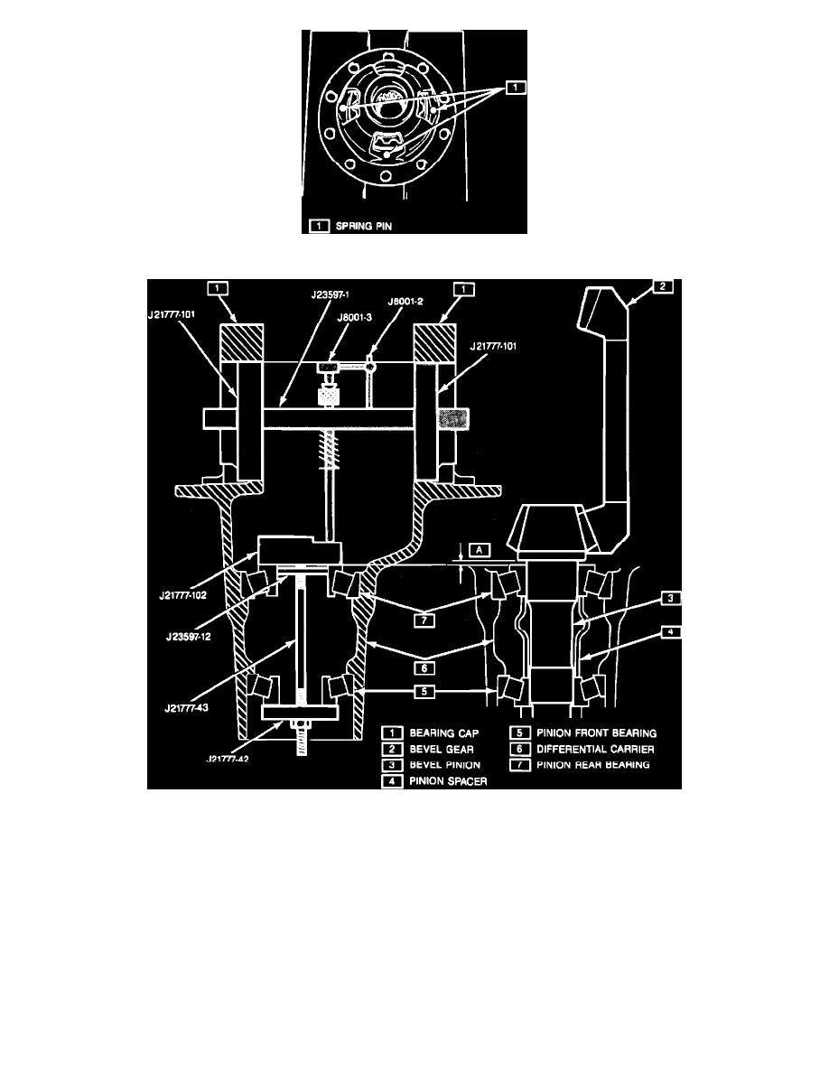
Fig. 10 Installing Spring Pins
Fig. 7 Bevel Pinion Mounting Distance
Use front differential procedure with the exception of the following:
1.
On 1991 models, remove rear wheel speed sensor then proceed as follows:
a.
Separate differential left case with rear wheel anti-lock brake exciter ring from right case.
b.
Remove exciter ring from left case using a suitable copper hammer. Tap evenly along the outer edge of exciter ring.
2.
Install rear wheel anti-lock brake exciter ring using a exciter ring installer tool No. J38891 or equivalent, a differential side bearing installer tool
No. J8107-04 or equivalent and a press.
3.
On all models, rear differential side bearing installation requires the use of bearing installer tool No. J37758 in place of J24433, or equivalent.
4.
Rear differential is a four pinion type. After installing pinions, align pinion shaft hole position with differential case and drive in three spring pins
until they are flush with the end surface of case, Fig. 10.
5.
Use the high step on pinion setting gauge tool No. J21777-102, or equivalent gauge plate when setting pinion depth in rear differential, Fig. 7.