
Tracker 4x4 L4-1590cc 1.6L (1993)
Temperature Gauge: Testing and Inspection
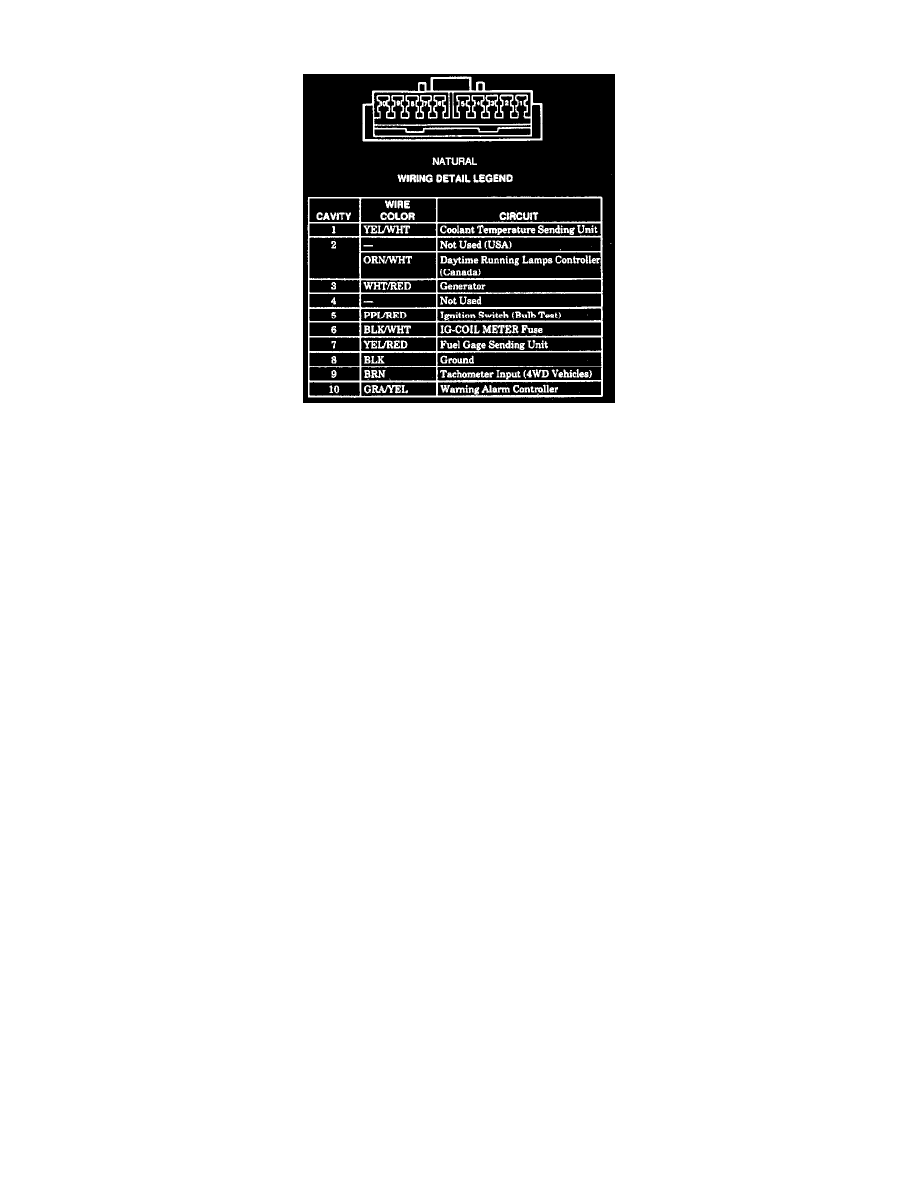
Fig. 8 Instrument Cluster C2 Connector Pin Location
1.
When gauge reads hot at all times, go on to step 3. When gauge reads cold with engine at normal operating temperature, disconnect sending unit
electrical connector, then install suitable jumper wire between connector and chassis ground, if gauge reads hot, replace sending unit, if gauge
reads cold, proceed to step 2.
2.
Disconnect instrument cluster C2 connector, then using suitable ohmmeter measure resistance between connector terminal No. 1, Fig. 8, and
chassis ground, if more than .3 ohms on 1990-91 models or 3 ohms on 1992-93 models is indicated, repair open in yellow/white wire between
cluster and sending unit. If less than .3 ohms on 1990-91 models or less than 3 ohms on 1992-93 models is indicated, inspect instrument panel
cluster panel circuit for cracks and poor connections, if ok, replace gauge.
3.
Disconnect sending unit electrical connector, if gauge reads cold, replace sending unit, if hot, disconnect cluster C2 connector, then using suitable
ohmmeter, measure resistance between connector terminal No. 1 and chassis ground, if resistance is infinite, inspect instrument panel cluster panel
circuit for cracks and poor connections, if ok, replace gauge. If resistance is not infinite, repair short to ground in yellow/white wire.