
Tracker 4x4 L4-1590cc 1.6L (1993)
TP Sensor Check
NOTE: Throttle valve must be closed.
TPS Adjustment
6.
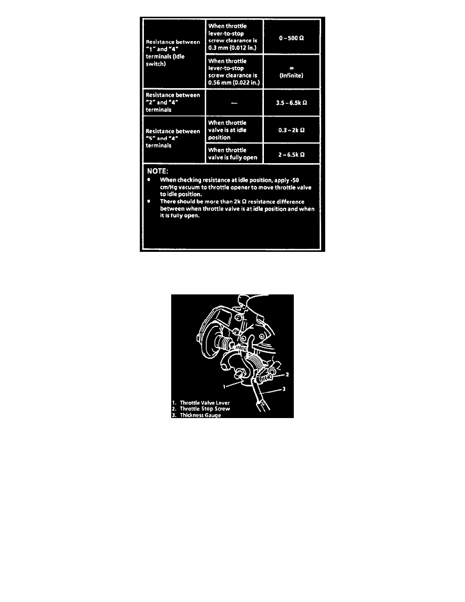
Insert a 0.4 mm (0.016 in) feeler gauge between the throttle stop screw and the throttle lever and with retaining screws loosely installed, turn TP
sensor fully clockwise, then slowly counterclockwise just until Ohmmeter indicates 12-18 ohms.
7.
In this position, tighten the throttle position sensor bolts to 3.5 N-m (2.5 ft. lb.).
8.
Remove feeler gauge. Ohmmeter should still indicate continuity.
9.
Insert 0.9 mm (0.035 in.) feeler gauge between throttle stop screw and throttle lever. Ohmmeter should now indicate an open circuit.
10.
Connect the throttle position sensor electrical connector securely.
11.
Reconnect the throttle opener vacuum hose to the SV valve.
12.
Reconnect the negative cable to the battery.