
C 3500 Truck 2WD V8-454 7.4L VIN J SFI (1999)
Circuit Description
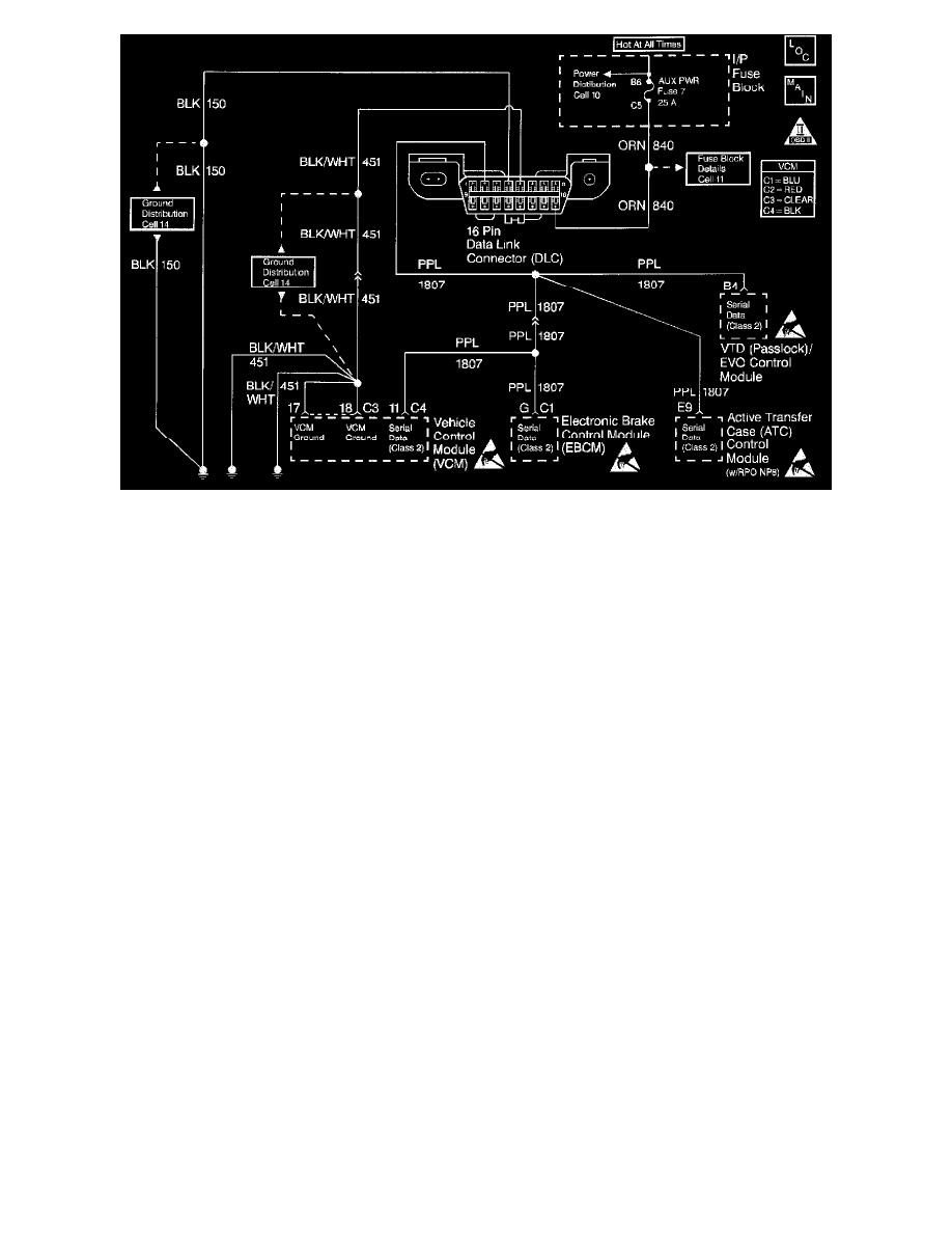
The Class 2 Serial Data circuit to the DLC allows bi-directional communication between the VCM and the scan tool. This is accomplished through pin 2
of the DLC. If communication between the scan tool and the VCM cannot be established, the procedure in the DLC Diagnosis table should be used to
diagnose the condition.
Diagnostic Aids
Check for the following items:
^
For the VCM to establish communication with the scan tool, system voltage must be between 9-16 volts. If the system voltage is not within this
range, refer to Charging System Check.
^
Ensure that the correct application (model year, truckline, VIN code) has been selected on the scan tool.
An intermittent may be caused by any of the following conditions:
^
A poor connection
^
Rubbed through wire insulation
^
A broken wire inside the insulation
Thoroughly check any circuitry that is suspected of causing the intermittent complaint. Refer to Intermittents and Poor Connections Diagnosis. See:
Testing and Inspection/Symptom Related Diagnostic Procedures
Test Description
The numbers below refer to step numbers on the Diagnostic Table.
2. This step determines if the scan tool is operating correctly.
6. This step monitors the actively communicating modules with the scan tools Diagnostic Circuit Check function. An active module is a module that
is successfully communicating on the Class 2 Serial Data line with the scan tool. An inactive module is a module which had previously established
communication with the scan tool, but currently is not communicating. If a module is not listed at all, then the module never successfully
established communications with the scan tool. Refer to A Diagnostic System Check-Data Link Communications in Data Link Communications.
7. This step isolates the VCM by disconnecting all the other components on the Class 2 Serial Data circuit. If VCM Class 2 Serial Data exists after
disconnecting all other components on the Class 2 Serial Data circuit, refer to A Diagnostic System Check-Data Link Communications in Data
Link Communications.
12. This step determines if voltage is not available at the DLC due to an open battery feed fuse. If the fuse is open, determine if the open was due to a
short in the battery feed circuit before replacing the fuse.
Overview
The OBD II vehicles have three options available in the scan tool DTC mode in order to display the enhanced information available. A description of the
new modes, the DTC Info and the Specific DTC, follows. After selecting the DTC, the following menu appears: