
Canyon 2WD L5-3.5L VIN 6 (2004)
Accessory Delay Module: Scan Tool Testing and Procedures
Scan Tool Data Definitions
SCAN TOOL DATA DEFINITIONS
DATA
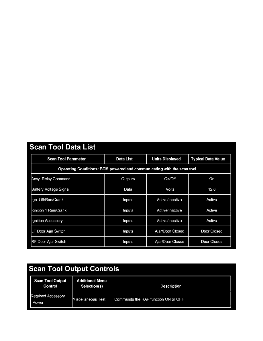
Battery Voltage Signal: The scan tool displays the battery voltage.
INPUTS
Ign. Off/Run/Crank: The body control module (BCM) uses this data in order to determine the position of the ignition switch. The scan tool displays
ACTIVE when the ignition switch is in the OFF, RUN or CRANK position.
Ignition 1 Run/Crank: The BCM uses this data in order to determine the position of the ignition switch. The scan tool displays ACTIVE when the
ignition switch is in the RUN or CRANK position.
Ignition Accessory: The BCM uses this data in order to determine the position of the ignition switch. The scan tool displays ACTIVE when the
ignition switch is in the accessory position only.
LF Door Ajar Switch.: The scan tool displays the position of the drivers door. The scan tool displays Ajar when the drivers door is open.
RF Door Ajar Switch.: The scan tool displays the position of the drivers door. The scan tool displays Ajar when the passenger door is open.
OUTPUTS
Accy. Relay Command: The scan tool displays the commanded state of the RAP relay. The scan tool displays ON when the BCM provides ground
to the RAP relay control circuit. The BCM will allow operation of the radio windshield wipers and the power windows with the ignition OFF and the
doors closed for up to 1198 seconds (approximately 20 minutes).
Scan Tool Data List
Scan Tool Output Controls