
Envoy 4WD L6-4.2L (2008)
Alarm Module: Testing and Inspection
Content Theft Deterrent (CTD) Does Not Disarm with Key Lock
Content Theft Deterrent (CTD) Does Not Disarm with Key Lock
Diagnostic Instructions
*
Perform the Diagnostic System Check - Vehicle prior to using this diagnostic procedure. See: Testing and Inspection/Initial Inspection and
Diagnostic Overview/Diagnostic System Check - Vehicle
*
Review Strategy Based Diagnosis for an overview of the diagnostic approach.
*
Diagnostic Procedure Instructions provides an overview of each diagnostic category.
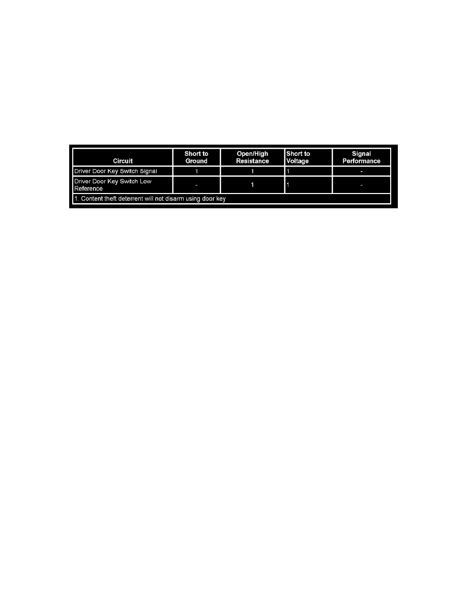
Diagnostic Fault Information
Circuit/System Description
The content theft deterrent (CTD) system is a software based system in which the body control module (BCM) actively monitors certain inputs to
determine if unauthorized vehicle access is being attempted. The driver door lock cylinder switch is used as an input to disarm the CTD system. The
driver door module (DDM) monitors the driver door key switch signal circuit to determine if the driver door cylinder is being rotated, indicating a
vehicle key is being used to unlock the vehicle and the CTD system should be disarmed. The door key cylinder switch, located in the door latch
assembly, provides a switched ground for the signal circuit. The DDM communicates the status of the driver door key switch to the BCM via serial data.
Circuit/System Verification
Ignition ON, verify the scan tool Door Key Switch parameter cycles between Active and Inactive while turning the driver door lock cylinder with the
vehicle key.
Circuit/System Testing
1. Ignition OFF, disconnect the harness connector at the driver door latch assembly.
2. Ignition OFF, test for less than 10 ohms of resistance between the low reference circuit terminal A and ground.
^
If greater than the specified range, test the low reference circuit for an open/high resistance. If the circuit tests normal, replace the DDM.
3. Ignition ON, verify the scan tool Door Key Switch parameter is Inactive.
^
If not the specified value, test the signal circuit terminal B for a short to ground. If the circuit tests normal, replace the DDM.
4. Install a 3A fused jumper wire between the signal circuit terminal B and ground. Verify the scan tool Door Key Switch parameter is Active.
^
If not the specified value, test the signal circuit for a short to voltage or an open/high resistance. If the circuit tests normal, replace the DDM.
5. If all circuits test normal, test or replace the driver door latch assembly.
Component Testing
1. Ignition OFF, disconnect the harness connector at the driver door latch assembly.
2. Test for infinite resistance between the signal terminal B and the low reference terminal A with the switch in the open position.
^
If not the specified value, replace the driver door latch assembly.
3. Test for less than 2.0 ohms of resistance between the signal terminal B and the low reference terminal A with the switch in the closed position.
^
If greater than the specified range, replace the driver door latch assembly.
4. Test for infinite resistance between each terminal and the driver door latch assembly housing/case.