
Envoy 4WD V8-5.3L VIN P (2004)
Steps 13-24
The numbers below refer to the step numbers on the diagnostic table.
4. Verifies that the body control module (BCM) is providing ground to the horn relay.
5. Tests for voltage at the battery positive voltage terminal of the horn relay coil.
7. Tests for voltage at the battery positive voltage terminal of the horn relay switch. The HORN fuse supplies power to the battery positive voltage
terminal of the horn relay switch.
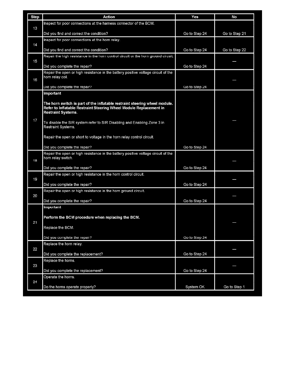
15. The horns need maximum current flow to operate properly. A high resistance (greater than 0.5 ohms) in the horn control circuit or the horn ground
circuit could cause operating problems with the horns. Check the circuits for faults that would restrict current flow.
17. The horn relay control circuit includes the horn switch. The horn switch is part of the inflatable restraint steering wheel module. The horn switch