
K 1500 Truck 4WD V8-350 5.7L (1986)
radius of 0.1 inch (2.54 mm) at the flange-to-nose transition (Figure 1), instead of the intended 1.0 inch (25.4 mm) nominal radius (Figure 2). All
right hand lower control arms have the proper radius and may be used for comparison.
NOTICE:
Some 85/86 vehicles may have had their lower control arms replaced. If inspection of the left lower control arm indicates the 1.0 inch (25.4 mm)
nominal radius shown in Figure 2, the control arm will NOT require a reinforcement kit. Submit a Product Campaign claim for INSPECT CONTROL
ARM no action required.
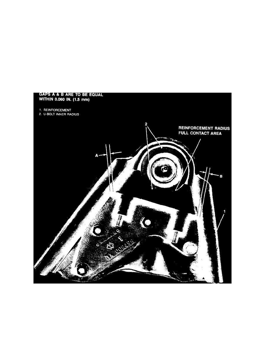
INITIAL POSITIONING OF THE REINFORCEMENT
1.
Clean the left hand lower control arm of all dirt, rust, grease, and undercoating from the spring pocket outboard. Clean both the top and bottom
areas of the control arm. This will insure good mechanical contact of the reinforcement and U-bolt to the control arm and ball joint flange. Use
appropriate solvents and/or a wire brush as required.
NOTICE:
If the control arm and the reinforcement are not thoroughly cleaned, the U-bolt may "walk" off the bottom of the bag joint when it is tightened.
2.
Center the reinforcement (Figure 3B "1") between the flanges. Gaps A & B (Figure 3B) are to be equal within 0.060 inch (1.5 mm). Secure the
reinforcement with a "C" clamp.
Important
The reinforcement is installed CORRECTLY when the ball joint makes full contact with the reinforcement radius (Figure 3B), not just in the center
section of the reinforcement.
The reinforcement is designed to fit ball joints with a bottom diameter of 2.60 inches (66 mm) or greater. The technician may find that the ball joint does