
K 1500 Truck 4WD V8-393 6.5L DSL VIN P (1995)
A.
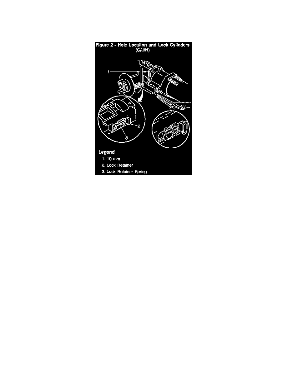
On G, J and N Models:
DO NOT REMOVE THE STEERING COLUMN as indicated in the Service Manual procedure.
1.
Remove the tilt lever, upper and lower column covers.
2.
Drill hole in module housing as indicated in the illustration using a short drill bit (1/8" followed by 9/32") and 90 degree drill motor or go degree
drill attachment to break or access the retaining spring for the lock cylinder button, see Figure 2.
3.
Using a pick or needle nose pliers, remove the retaining spring from the hole.
4.
Using pliers, grasp and remove the retaining button for the cylinder.
5.
Remove the cylinder from the housing.
6.
Follow the procedures in the General Information Section of the appropriate vehicle Service Manual when recoding of cylinders is required.
7.
Install the new cylinder and reinstall the steering column components.
B.
On U, W, and light duty trucks, follow the Service Manual procedure for keys missing, or cylinders won't rotate.
Procedure: Instrument Panel Mounted Switches
Important:
This new procedure involves drilling a hole through the plastic ignition switch and into the lock cylinder slightly to break or access a cylinder
release button retaining spring (similar to G, J and N models). The removal of the broken spring and then the release button will allow the switch
to be reused.
1.
Remove the necessary trim panels to gain access to the instrument panel mounted switch (refer to information in "Body and Accessories Section,
Instrument Panel, Gauges and Consoles").
a.
On instrument panel mounted N models (Malibu and Cutlass), the switch and cylinder can be accessed after removing the instrument cluster
assembly and positioning the switch/cylinder upward in the cavity for the cluster assembly.
b.
On Corvette models, the switch and cylinder can be accessed after removing the knee bolster from the lower instrument panel area and
positioning the switch/cylinder downward from its location on the instrument panel.
2.
Loosen switch from instrument panel and disconnect the electrical connections, BUT NOT the cable connection for BTSI (Brake/Transmission
Shift Interlock).
3.
Protect the immediate work area with a fender cover or other suitable material.