
K 2500 Suburban 4WD V8-454 7.4L (1994)
Vehicle Speed Sensor: Description and Operation
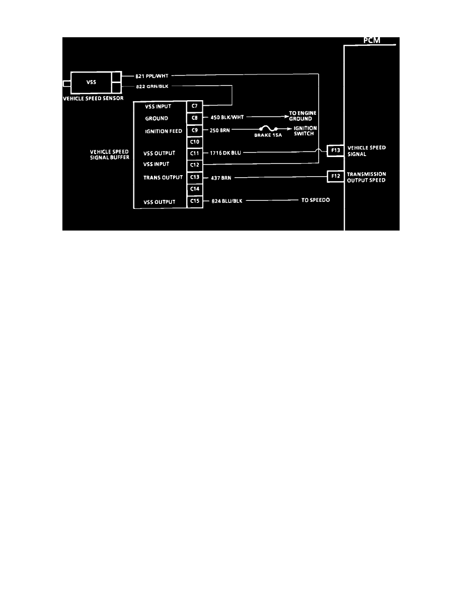
VSS Buffer Circuit Wiring Diagram
Purpose:
The Vehicle Speed Sensor (VSS) is made up of a coil, which is mounted on the transmission, and a tooth rotor which is mounted to the output
shaft in the transmission. As each rotor tooth nears the coil, the coil produces an Alternating Current (AC) voltage pulse. As the vehicle speed
increases, the number of AC voltage pulses increase. The VSS signal buffer processes inputs from the VSS and output signal to the speedometer
control module, and cruise control module. The VSS buffer signal takes the voltage pulses from the VSS and uses them to open and close four
solid state output switches to ground at a rate proportional to vehicle speed. The VSS buffer is matched to the vehicle based on final drive ratio
and tire size. It is important to ensure that the correct VSS buffer is installed in the vehicle if replacement is necessary.