
K 2500 Truck 4WD V8-379 6.2L DSL VIN C FI (1989)
1.
Remove lower steering trim panel.
2.
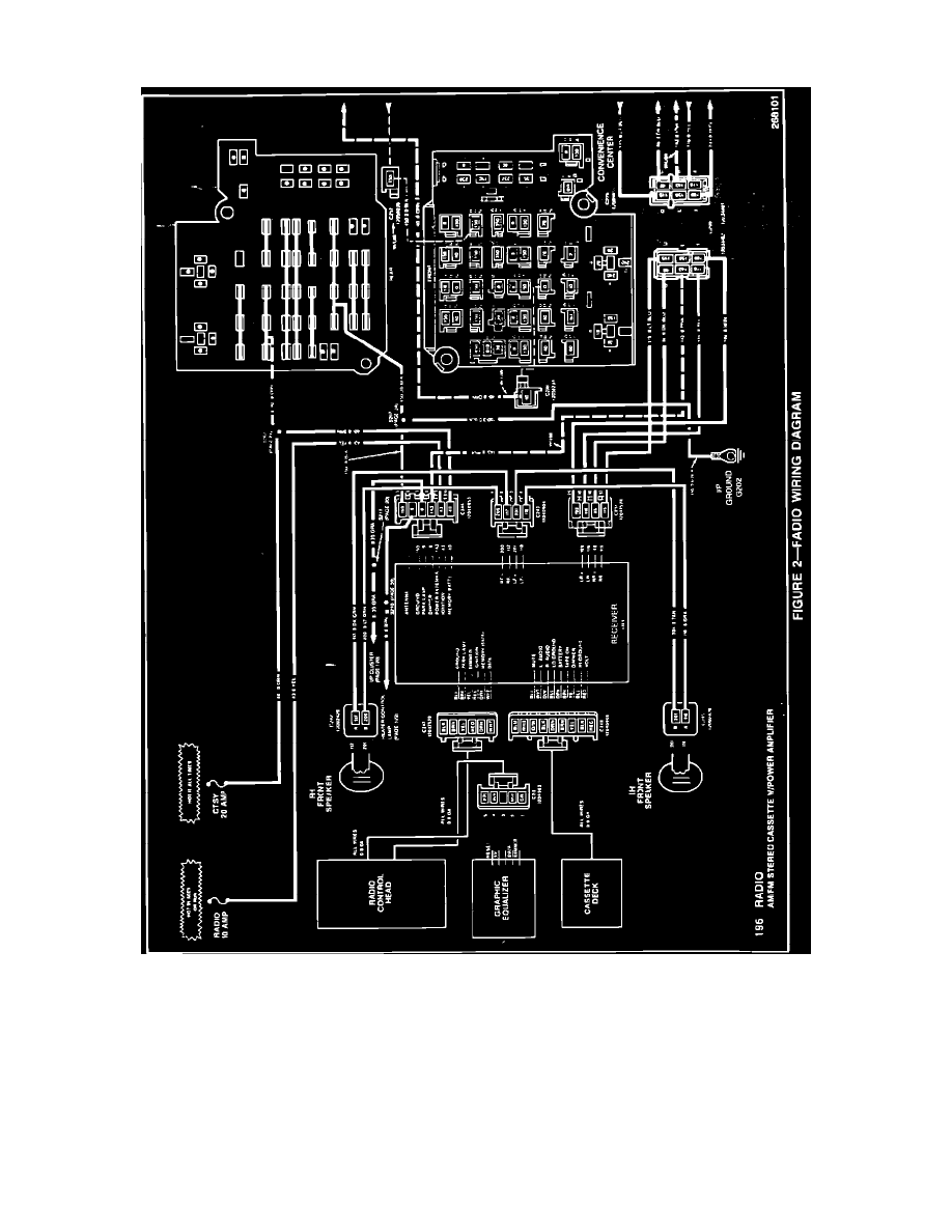
Locate the six wire connector going into the bottom of the radio receiver at location C247. Please refer to the appropriate 1992 ELECTRICAL
DIAGRAM AND DIAGNOSIS MANUAL (Figure 2).
3.
Locate the white wire (pin 6) in this six wire connector. Also locate the unused pin in the seventh position on the radio receiver. Both the white
wire in the sixth position and the open unused seventh pin are serial data terminals. The open pin on the radio receiver in position seven is not
shown on the electrical wiring diagram. The six wire connector is visible from under the dash and is quite accessible.
4.
Using a 16-inch piece of 0.8 GA wire, make a jumper wire to install between ALDL terminal J and the open seventh position pin of the radio
receiver. Use a wire with white insulation to indicate a serial data line.
The connection at the ALDL location can be made with terminal part number 12077411. The connection at the radio receiver can be made with
terminal part number 12047767. These terminals are included in Packard Electric terminal repair kit J38125.