
K 2500 Truck 4WD V8-379 6.2L DSL VIN C FI (1989)
Timing Cover: Service and Repair
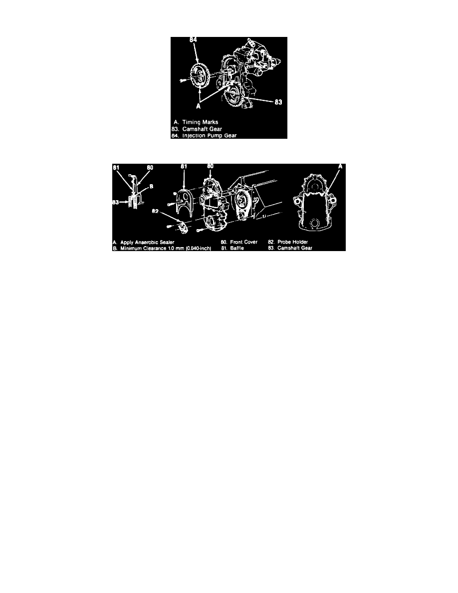
Fig. 10 Injection Pump Gear & Gear Timing Marks
Fig. 11 Front Cover & Components
1.
Drain engine block and remove water pump.
2.
Align marks on injection pump gear and camshaft gear, Fig. 10, then scribe mark aligning injection pump flange and front cover.
3.
Remove crank pulley, torsional damper, front cover to oil pan bolts, fuel return line clips and injection pump driven gear.
4.
Remove injection pump retaining nuts from front cover.
5.
Remove baffle, remaining cover bolts and front cover, Fig. 11.
6.
Reverse procedure to install, noting the following:
a. Apply a 3/32 bead of anaerobic sealant No. 1052357 or equivalent, around sealing surface as shown in Fig. 11..
b. Apply a 3/16 bead of RTV sealant around bottom portion of front cover which attaches to oil pan.
c. Ensure scribe marks on injection pump and front cover are aligned and marks on cam gear and pump gear are aligned.
d. Tighten bolts/nuts to specifications.
e. After torquing bolts and nuts, measure clearance between injection pump gear and baffle. It is necessary to maintain a minimum of .040 inch
between the gear and baffle or noise may result.