
K 2500 Truck 4WD V8-379 6.2L DSL VIN C FI (1989)
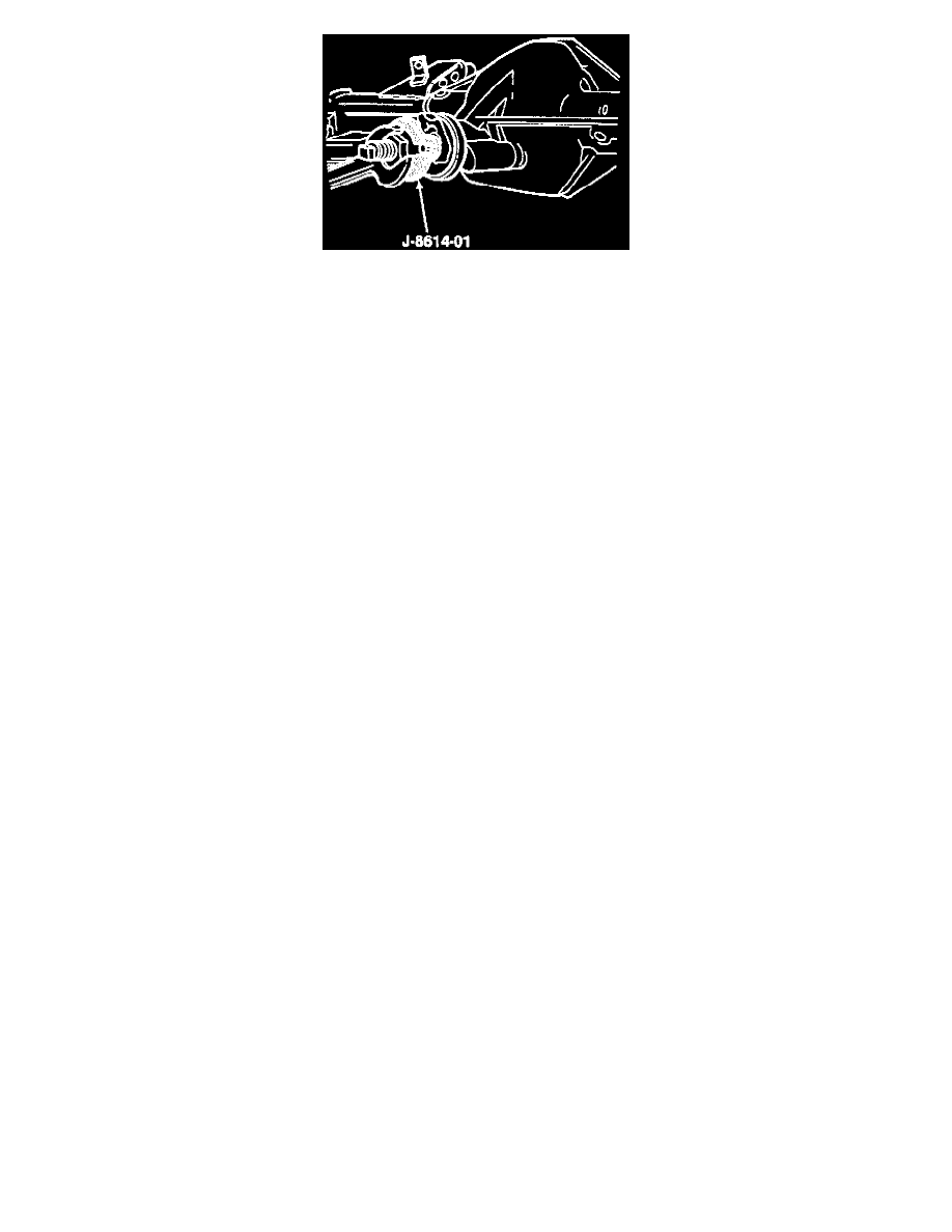
2. Pinion flange using J 8614-01.
-
Use scribed marks for installation.
Important: Do not attempt to hammer the pinion flange onto the pinion stem.
3. Washer and a new nut.
-
Tighten:
A. The nut on the pinion stem as close to the original marks as possible without going past the mark. Use the reference mark and the thread
count as reference.
B. The nut a little at a time and turn the pinion flange several times after each tightening to set the rollers.
Measure
-
Using an inch-pound torque wrench, the torque required to rotate the pinion. Compare this with the required rotating torque recorded earlier.
Continue tightening and measuring a little at a time until the same preload is achieved.
Important:
^
If the original preload torque value was less than 3 (inch lbs.) then reset the torque specification to 3-5 (inch lbs.).
^
Align the propeller shaft with the alignment marks made previously.
4. Propeller shaft.
5. Retainers and bolts.
-
Tighten bolts to 20 Nm (15 ft. lbs.).
6. Rear wheels and drums.
7. Lubricant to the rear axle as necessary.
Full-Floating Axle 10-1/2 Inch Ring Gear
^
Tools Required:
-
J 8614-01 Companion Flange Holder
-
J 8614-02 Companion Flange Remover
-
J 24384 Pinion Oil Seal Installer (American Axle 10 1/2 inch ring gear axle).
^
The pinion oil seal and the companion flange may be replaced with the carrier assembly installed in the vehicle.
REMOVE OR DISCONNECT
^
Raise the vehicle on a hoist and support with safety stands.
1. Axle shafts.
Important:
^
It is essential that the positions of all driveline components relative to the propeller shaft and axles be observed and accurately reference
marked prior to disassembly. These components Include the propeller shafts, drive axles, pinion flanges, output shafts, etc. All components
must be reassembled in the exact relationship to each other as they were when removed. Specifications and torque values, as well as any
measurements made prior to disassembly, must be followed.
^
Accurately mark the installed position of the rear propeller shaft.
2. Propeller shaft.
A. Use a piece of tape to hold the bearing caps.
B. Secure the propeller shaft up and out of the way so as not to put unnecessary stress on the universal joints.