
K 2500 Truck 4WD V8-379 6.2L DSL VIN C FI (1989)
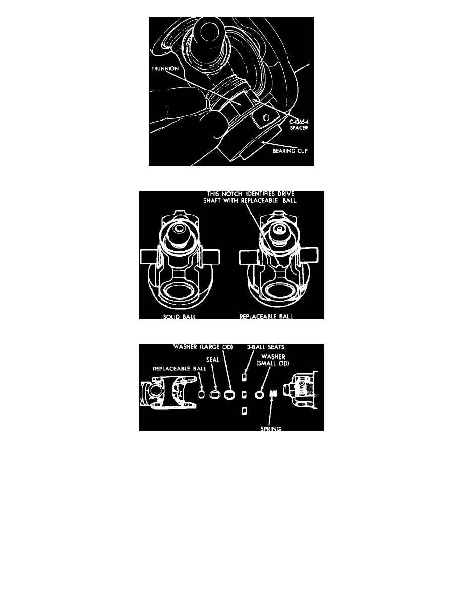
Fig. 14 Using Spacer To Completely Drive Out Bearing Cup
Fig. 15 Solid Ball & Replaceable Balls. Notch Identifies Driveshaft With Replaceable Ball
Fig. 16 Exploded View Of Ball & Seat
DISASSEMBLY
Constant Velocity Joint
To disassemble the constant velocity joint, the bearing cups should be removed in sequence shown in Fig. 11. This method requires the least amount
of work.
1.
Mark all yokes before disassembly as shown in Fig. 12, so that they can be reassembled in their original relationship to maintain driveshaft
balance. The following procedure can be performed in a vise. A cross press tool, Fig. 13, can be used in place of the socket used to drive the
bearing cups.
2.
Support the driveshaft horizontally in line with the base plate of a press. Place rear end of coupling yoke over a 1-1/8 inch socket to accept the
bearing cup. Place a socket slightly smaller than the bearing cup, on the opposite side of the spider.
3.
Press bearing cup out of coupling yoke ear. If bearing cup is not completely removed, insert spacer C-4365-4 or equivalent, Fig. 14, and complete
removal of bearing cup.
4.
Rotate driveshaft 180° and shear the opposite retaining ring, and press the bearing cup out of the coupling yoke as described previously, using
spacer C-4365-4 or equivalent.